Facebook
 Google
 GitHub
 Linkedin
Motor Starters Part 5: Pros and Cons of Soft Starters
This introduction to soft starters, which utilize voltage reduction, will address working principles, provide wiring diagrams, and feature the advantages and disadvantages of the technology.
To catch up on this series on motor starters, please visit the following links:
- Motor Starters Part 1: Direct On-line
- Motor Starters Part 2: Selecting and Sizing DOL Parts
- Motor Starters Part 3: Pros and Cons of the Star-Delta Configuration
- Motor Starters Part 4: Selecting and Sizing Star-Delta Parts
Different types of equipment and machines power industries. Among them is induction–the most used machine in the industry, accounting for a staggering 70% of all motors used in modern industries. The robustness and efficiency give them advantages over other motors used in the industrial sector. These devices require advanced protection against voltage surges and other damages during operation and prevent eventualities that may damage the induction motor and increase its durability. The motor starter is the most frequently used equipment to protect the induction motor. This article will focus on the soft starter.

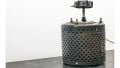
Image used courtesy of Adobe Stock
Soft Starter
A soft starter utilizes voltage reduction during motor startup, gradually increasing the voltage. This helps the motor accelerate slowly and smoothly pick up speed. It also protects the motor against mechanical tears due to a full voltage supply. In other words, a soft starter is an electric device that reduces the motor starting torque and slowly increases it until it safely achieves the motor-rated speed.
Soft Starter Diagram

Figure 1. Soft starter diagram. Image used courtesy of Simon Mugo
For the three-phase motor of induction type, two thyristors are connected in every phase in an anti-parallel mode. Therefore, the total number of thyristors used is six. The thyristors are controlled by a separately connected logic circuit, either a microcontroller or a PID controller. The logic circuit gets its power from the rectifier circuit powered by the main. Observe Figure 1 for more understanding. The soft starter parts include power switches, protection gadgets such as the fuse, an overload relay for overcurrent protection, and a magnetic contactor used for isolation. In the same circuit is the bypass switch, which is vital for full voltage resumption across the induction motor once it gets to a fully rated speed.
Soft Starter Working Principle
In a soft starter, a thyristor is the main component necessary for voltage control. This is a controlled rectifier. It starts current flow conduction in one direction when there is an applied gate pulse known as a firing pulse.
When carrying out the soft start, an electric signal is passed through the SCRs such that only the last sinus curve half period passes through. During this start, the electric signal is passed earlier, allowing bigger voltage parts to cross through the SCRs. Eventually, after passing a zero, the firing signal is passed, allowing all the voltage to pass across the thyristor too.
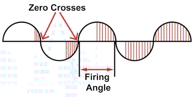
Figure 2. Thyristor firing waveform. Image used courtesy of Simon Mugo
During the process of soft stop, the process is the opposite of the soft start. At the start, full voltage passes through the SCRs, and as the process of stopping proceeds, the firing signal is sent in a delayed mode allowing less voltage to go through the SCR until it gets to zero. After that, the motor receives zero voltage and comes to a stop.
Soft Starter Wiring Diagrams
In-Line Connection
It is also referred to as a standard connection. The motor control for protection and isolation and the soft starter are perfectly connected in series. Three leads connect the motor to the soft starter. See Figure 3 below for an illustration.

Figure 3. Standard soft starter wiring. Image used courtesy of Simon Mugo
\[I_{soft-starter}=I_{full-current}\]
Inside Delta Connection
This is similar to what we did in the star-delta starters. The phase terminals of the soft starter are connected such that they are in series with each winding of the motor. The soft starter ends up carrying a phase current that is about 58% of the motor rated current. This method is only suitable for three-phase soft starters
\(I_{soft-starter}=\frac{I_{required}}{\sqrt{3}}=58\%\,of\, I_{required}.\) This is after the start
\(I_{soft-starter}=\frac{I_{required}}{1.5}=67\%\,of\, I_{required}.\) This is during the start

Figure 4. In-delta connection. Image used courtesy of Simon Mugo
Soft Starter Types
Currently, there are only five types of soft starters available.
Primary Resistor
This type has a resistor introduced in each current phase to resist current flow. On starting the motor, the resistor resists the current flow, causing a voltage drop. The primary resistor starters are good for smooth starts and have the advantage of offering two-point acceleration.
Auto Transformers
Auto transformers are one of the most effective ways of starting a motor using soft starting. The resistor in the primary resistor type is replaced with a transformer, and the starter has to utilize the transformer’s tapping to release power to the motor. They can supply higher current to the motor than other soft starter types.
Part Winding
In this method, the motor winding is divided into two or more sets. The identical set’s purpose is to achieve parallel operations. Power is applied to one set of motor windings. Immediately, the motor achieves the maximum speed, the other winding sets are powered to gain normal running. Here, reduced starting torques and currents are milestone achievements.
Wye Delta
This demands that the motor have connections to its three windings of the coil.
Solid State
As the newest method, mechanical components are replaced with electrical components. The SCR is the key component here, used to control the motor voltage when it is accelerating
Soft Starter Advantages
- Unlike other types of motors, offers gradual voltage increase hence a very smooth startup
- Zero power surge since it limits the amount of current passing as a time
- Motor acceleration and deceleration are adjustable by varying the soft starter firing angle
- Some motor applications require multiple starts or stops at several intervals; the soft starter can do this without multiple starts and stops
- Overheating is greatly reduced because it injects greatly low currents during startup
- Offers an increased lifespan compared to conventional starters due to its smooth operation and the eradication of mechanical and electrical stresses within the motor windings
- High and improved efficiency as compared to the conventional motors
Soft Starter Disadvantages
- It is impossible to regulate the speed
- It has a reduced starting torque
- It has problems with heat dissipation
Soft Starter Applications
- Conveyor Belts due to starting and stopping smoothness required
- Fans
- Motors that employ the use of belts and pulleys such as in posho mills
- Liquid or water pumps
Key Takeaways of Soft Starters
- A soft starter utilizes the voltage reduction principle to start a motor when it helps the motor accelerate slowly and smoothly until it gets to the maximum speed.
- A soft starter wiring diagram comprises the circuit breaker, contactor, thermal overload relays, thyristor firing circuit, bypass contactors, rectifiers and transformers, and a microcontroller.
- Soft starters can be wired in inline connection and inside delta connection methods.
- Several types of soft starters exist, including primary resistors, autotransformers, part winding, wye-delta, and solid-state.
- Soft starters run smoothly, have zero power surges, adjust motor acceleration and deceleration, reduce overheating, increase equipment lifespan, and improve efficiency.
- They find applications in conveyor belts, fans, belts, pulleys, and liquid pumps.