Facebook
 Google
 GitHub
 Linkedin
Substation Components—Part 5: Busbar Configurations
Here, we provide an overview of common substation busbar configurations—Single Bus, Main and Transfer, Double Breaker/Double Bus, Ring Bus/Ring Main, and Breaker and a Half.
Designing a substation involves not only the visible equipment and ratings but also the less apparent factors—operational flexibility, fault tolerance, and maintainability. The busbar configuration lies at the core of these tradeoffs. The “right” topology depends on voltage level, criticality of load, protection philosophy, expansion plans, and budget.
Single Bus System
The single bus is the simplest substation topology: every incoming and outgoing circuit connects to one common bus through its own circuit breaker and isolators. Variants include a sectionalized single bus, where one or more bus couplers divide the bus into segments to limit the extent of outages.
Layout: one energized bus; each feeder/generator/transformer bay has a breaker and isolators. Sectionalization adds a bus coupler breaker and isolators to split the bus into two or more sections.
Typical Use: small to medium substations where continuity is desirable but not critical—often MV switchboards and indoor 11 kV installations; sometimes employed with bus sectionalization to localize faults.
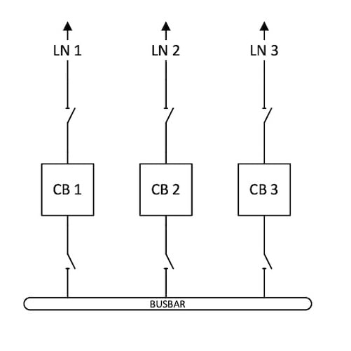
Figure 1. Single Bus system
Advantages
Simplicity: The single bus scheme offers simplicity, requiring minimal primary equipment, straightforward relaying, and intuitive operation.
Low cost and compact footprint: It is cost-effective and space-efficient, as each circuit uses only one breaker with limited steelwork and buswork, resulting in a compact overall layout.
Disadvantages
Low redundancy: any bus fault or maintenance requiring bus de‑energization interrupts all circuits connected to that bus; even with sectionalization, maintenance at the bay level typically still trips the associated circuit.
High exposure to bus faults: a single point of failure. In addition, a system fault can draw contributions from all sources tied to the bus, potentially raising fault duties.
A single bus serves well in cost‑sensitive projects, industrial plants with alternate feeders, or distribution substations where upstream redundancy exists. If maintenance windows are rare and outages expensive, consider at least a sectionalized bus—or step up to main and transfer.
Double Busbar (Main and Transfer) System
“Double bus” is a family of schemes. The most common economical variant in utility practice is the main and transfer bus: a normally energized main bus with a de‑energized transfer (auxiliary) bus. A single “bus tie” or “transfer” breaker can temporarily protect any circuit during breaker maintenance.
Normal operation: all circuits run from the main bus through their dedicated breakers.
Maintenance transfer: to remove a line breaker, operators open that breaker and its disconnects, close the circuit’s transfer switch to the auxiliary bus, close the transfer bus disconnects, and finally close the transfer (bus tie) breaker. The circuit continues in service, now protected by the transfer breaker.
Bus Couplers and Transfer Switches
The bus tie (transfer) breaker must be relayed to stand in for any line breaker, which complicates protection and interlocking compared to a single bus. Clear operating procedures are essential to prevent errors during the changeover.
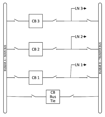
Figure 2. Main and Transfer Busbar scheme
Advantages
The main and transfer busbar scheme offers several advantages. It allows breaker maintenance without interrupting the associated circuit, ensuring continued operation during maintenance activities. The arrangement also requires modest land area, making it suitable for space-constrained sites. Additionally, it provides good expandability at a low incremental cost (still essentially one breaker per circuit plus the transfer breaker).
Tradeoffs
Reliability: a main bus fault still drops all circuits on that bus; protection and switching complexity increase; and the bus tie protection must be versatile. This scheme is common at 230 kV and below and in older stations; sectionalizing the main bus can limit the impact area.
Main and transfer suits sites where breaker maintenance flexibility is required, budgets are constrained, but a bus fault–tolerant arrangement (like ring or breaker‑and‑a‑half) is not yet justified.
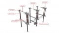
Double Breaker/Double Bus Scheme
The double breaker/double bus (DB/DB) scheme is one of the most robust high-voltage substation arrangements used where continuity of service is critical. By providing each circuit with two dedicated circuit breakers—one to each of two main buses—it enables ride-through of a single bus fault, facilitates maintenance without load interruption, and delivers exceptional operational flexibility. While the scheme’s cost and footprint are higher than simpler arrangements, its reliability and maintainability make it a preferred configuration at critical transmission nodes, major load centers, and generator switchyards.
The Core Topology
The DB/DB scheme consists of:
- Two independent main buses: Bus A and Bus B.
- For each circuit (line, transformer, or reactor), two dedicated breakers: Breaker-A connecting the circuit to Bus A, and Breaker-B connecting the circuit to Bus B.
- Disconnectors (isolators) on each side of the breakers to enable safe isolation for maintenance.
- Busbar protection zones established separately for Bus A and Bus B.
The circuit’s connection point sits electrically between the two breakers, so that either breaker can connect it to its respective bus. Depending on the operating philosophy, one or both breakers can be closed. With both closed, the circuit is simultaneously tied to both buses; with one closed, it is assigned to a specific bus while the other breaker provides hot-standby redundancy.
This arrangement ensures that a fault on one bus requires tripping only the breaker leading to that bus, leaving the circuit still energized via the healthy bus. When properly engineered with fast bus differential protection and coordinated breaker failure logic, the circuit experiences either no interruption or a sub-cycle dip during a bus fault event.
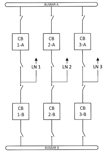
Figure 3. Double-Breaker Double Bus scheme
Advantages
Bus fault ride-through: The circuit stays energized via the healthy bus when the other bus faults or is taken out of service, maximizing continuity of supply to critical loads or transmission corridors.
Full breaker redundancy per circuit: Each circuit has two dedicated breakers, allowing maintenance or failure of one without forcing an outage of the circuit.
Clear protection zoning: Each breaker belongs to one circuit; there is no sharing of breakers between bays. This simplifies protection logic compared to arrangements that share breakers, and it reduces interdependencies during testing and maintenance.
Operational flexibility: Operators can hot-transfer circuits between buses, parallel buses temporarily for load sharing or switching, and isolate equipment with minimal switching steps.
Maintenance: Breaker or disconnector maintenance can often proceed with the circuit energized via the opposite bus, reducing planned outage hours and improving availability metrics.
Practical Limitations
Capital cost: Two breakers per circuit, dual sets of disconnectors, and added control/protection hardware increase cost substantially compared to simpler schemes.
Footprint: In air-insulated switchgear (AIS), the physical space for two breakers and additional bus connections per bay increases the site length and width. While gas-insulated switchgear (GIS) mitigates footprint, it can further elevate capital cost.
System studies complexity: Operating with both breakers closed on many bays parallels the buses at multiple points, potentially creating circulating currents and complicating bus differential protection. Operators often standardize on a single-bus assignment mode in steady-state to limit these effects.
CT and protection coordination: With two breakers in the current path for a single circuit, protection must correctly sum or select currents, account for breaker status, and avoid misoperations during asymmetric configurations.
Ring Main / Ring Bus Configuration
Engineers use the term “ring main” in two related contexts:
- Medium‑voltage distribution rings in urban networks, realized with compact ring main units (RMUs).
- Transmission‑level ring bus substations, where breakers are arranged in a closed loop with circuits tapped between adjacent breakers.
In a ring, current can reach any circuit by two paths. Under normal conditions, all ring breakers are closed, allowing flexible load sharing. A fault on a circuit trips the two adjacent breakers, isolating only that segment while keeping the remainder of the ring alive.
RMUs package two load‑break switches (to connect to each side of the ring) and a transformer protection device in a metal‑enclosed, often gas‑ or solid‑insulated unit. They’re standard in MV distribution from roughly 7.2 to 36 kV and are designed for outdoor or compact indoor siting—typical ratings include 630 A busbars with short‑time withstand up to 25 kA for 1 s. These features make RMUs the building blocks of dense urban rings.
Fault isolation Advantages
Ring bus substations isolate a faulted circuit by opening its two adjacent breakers; the rest of the system remains energized. Breaker maintenance can be done without interrupting any circuit because the ring remains closed around the out‑of‑service bay. The scheme scales naturally to about three to five circuits, and can evolve into a breaker‑and‑a‑half as circuits are added.
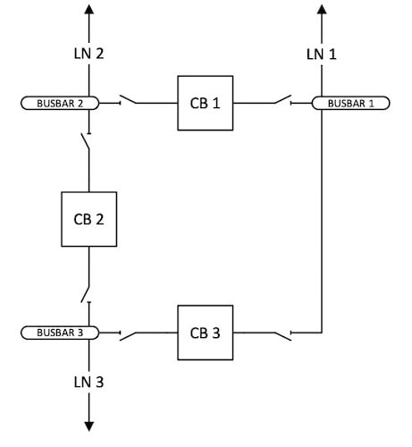
Figure 4. Ring Bus configuration
Operational Challenges
Reduced reliability during open‑ring operation: once the ring is broken (for maintenance or following a fault), a subsequent outage may cut more circuits if the “source–load” pattern is unfavorable. Careful alternation of sources and loads around the ring mitigates the risk.
Protection coordination: in MV rings—especially with distributed energy resources (DER)—fault currents can be bidirectional and vary with operating state. Directional overcurrent elements and adaptive settings are often required; high DER penetration can cause selectivity loss, false trips, or “relay blindness” if not accounted for in coordination studies.
Stability and loading: power flows in closed rings can shift in unintuitive ways after a section opens, potentially overloading remaining sections if contingency planning is weak. System studies should verify thermal margins for single‑contingency open‑ring operation.
Breaker and a Half Scheme
The breaker and a half configuration is a standard design in EHV/HV switchyards. Each bay contains three breakers connecting two main buses; two circuits terminate between the three breakers, sharing the center breaker. In effect, there are 1.5 breakers per circuit.
Reliability: a bus fault trips the associated bus without interrupting any circuit; each circuit remains fed from the healthy bus via its two breakers. Any breaker (including the shared center one) can be isolated for maintenance with no service interruption to other circuits; a failure of an outside breaker typically trips only its own circuit, while a center‑breaker failure trips both circuits in that bay.
Operational flexibility: both buses are normally energized; sources and loads are often arranged on opposite sides of the bays to balance flows and contingency behavior.
Cost and Relay Complexity
Compared to main‑and‑transfer, breaker and a half needs more breakers and a richer protection scheme. The center breaker must respond correctly to faults on either adjacent circuit, and each circuit typically has its own VT source for relaying. Despite this complexity, the scheme’s reliability makes it the go‑to for important transmission nodes.
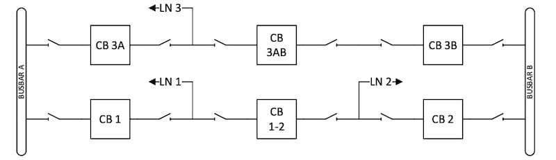
Figure 5. Breaker and a Half scheme
Comparison to a Double Bus, Double Breaker
Double‑breaker/double‑bus assigns two dedicated breakers per circuit—top‑tier reliability and maintainability, but the highest cost. Breaker and a half offers almost all the functional benefits at a lower cost per circuit, which is why utilities commonly favor it for transmission substations over the double‑breaker/double‑bus alternative.
The breaker-and-a-half configuration is particularly well-suited for high-importance nodes such as generation interconnections, EHV switching stations, and large HV substations, where the ability to ride through bus faults, perform live maintenance, and accommodate future expansion is essential.
Comparative Analysis of Busbar Configurations
Table 1 below presents a qualitative comparison of various busbar configurations based on key operational parameters, including reliability, maintenance flexibility, and expandability.
| Configuration | Reliability / Fault Tolerance | Maintenance Flexibility | Expandability | Typical Use |
| Single Bus | Low — Bus fault trips all connected circuits | Low — Bay maintenance trips associated circuit; bus maintenance causes multiple outages | Easy — Add bays easily, but no redundancy | Small/MV substations, process plants, or sites with upstream redundancy |
| Main & Transfer (Double Bus, Single Breaker) | Moderate — Breaker maintenance without outage; bus fault still extensive | Good — Breaker maintenance possible; transfer procedures add complexity | Good — Add bays and sectionalize the main bus as needed | Distribution to sub-transmission nodes (≤230 kV), legacy stations, budget-constrained upgrades |
| Ring Bus / Ring Main | Good — Faulted section isolated with two breakers; open-ring reduces margin | Very Good — Breaker/circuit maintenance possible without outages | Moderate — Practical limit ≈ 3–5 circuits before evolving to breaker-and-a-half | HV substations with modest circuit count |
| Breaker-and-a-Half | High — Bus faults do not interrupt circuits; tolerates most single breaker failures | Excellent — Live maintenance possible for any breaker or bus | Excellent — Add bays easily as the system grows | EHV/HV backbone substations, critical interconnections |
| Double Breaker–Double Bus | Very High — Each circuit has two dedicated breakers; full redundancy against bus or breaker failure | Excellent — Any breaker or bus can be maintained without circuit interruption
|
Good to Excellent — Additional circuits require significant space and cost, but integrate seamlessly
|
Top-tier generation switchyards, major transmission hubs, and stations demanding maximum reliability
|
Practical Selection Consideration
Match topology to consequence of failure. If a bus fault would trigger significant load shedding or cascading effects, a single-bus configuration should be avoided unless the associated risk can be tolerated or mitigated through sectionalization and strong upstream redundancy.
Consider operational complexity and protection. Main‑and‑transfer introduces transfer procedures and versatile bus‑tie relaying; ring configurations require careful directional coordination, especially with DER. Breaker-and-a-half requires more sophisticated protection schemes and instrument transformers, but provides significantly higher system reliability and operational flexibility.
Plan for evolution. It’s common to build a ring bus initially and convert to a breaker‑and‑a‑half as circuits accumulate. Similarly, an MV radial can be tightened into a ring over time with RMUs to improve continuity.
Equipment ratings. Typical MV RMUs are rated up to 36 kV, 630 A busbar continuous, and 16–25 kA short‑time—adequate for most urban feeders but not for high‑fault‑level nodes without upstream limitation. Verify manufacturer data and system fault studies.
Key Takeaways
There is no universally “best” busbar configuration—only one whose failure modes, maintenance options, and lifecycle costs align with the system’s risk profile and growth path. Single bus is the benchmark for simplicity and cost; main and transfer adds breaker maintenance flexibility without solving the bus fault exposure; ring arrangements bring strong continuity and a natural upgrade path to breaker‑and‑a‑half; and the one‑and‑a‑half breaker scheme is the workhorse for high‑reliability EHV/HV nodes.
In evaluating busbar configurations, it is essential to establish clear performance objectives—such as fault ride-through capability, maintenance strategy, and expandability—and to assess each scheme against realistic contingencies and protection constraints, including DER-driven bidirectional flows in MV rings. The right topology will make future work—adding circuits, swapping breakers, taking buses out for inspection—an operational routine rather than a reliability event.
Featured image from Adobe Stock (licensed).
All images used courtesy of Idaho National Laboratory (INL).