 Facebook
 Google
 GitHub
 Linkedin
Motor Starters Part 3: Pros and Cons of the Star-Delta Configuration
This article introduces the composition, advantages, and disadvantages of star-delta motor starters.
In the area of power electronics, most induction motors use direct on-line starters. Starting very large electrical motors using the direct on-line (DOL) method is a challenge. In particular, the direct on-line (DOL) method causes voltage disturbances on the voltage supply line due to the drawing of very large currents.
To overcome this challenge, large electrical induction motors are powered on at a reduced starting voltage. Full voltage reconnection occurs when the motor operates near its maximum speed. The process of reducing this voltage can be achieved through two starting methods: the auto-transformer and the star-delta. This article will focus on the star-delta method.
Star-Delta Motor Starter Parts
The star-delta motor starter comprises the following elements:
- Contactors used for switching the motor
- Overload relays for overload protection of the motor against voltage and currents overload
- Circuit breakers/fuses to protect the motor and other components against short circuits
- A timer for switching between the star connection and the delta connection.
Star-Delta Motor Starter Working Principle
The electric circuit shown in Figure 1 is a typical star-delta motor starter. The circuit includes the protection fuses, F1, and overload protection relays, F2. It also comprises three magnetic contactors: the main contactor K1, delta-connected contactor K2, and star-connected contactor K3. The motor terminals U1, V1, and W1 connect to K1 via the thermal overload protection relay F2, while terminals U2, V2, and W2 connect to contactors K2 and K3.
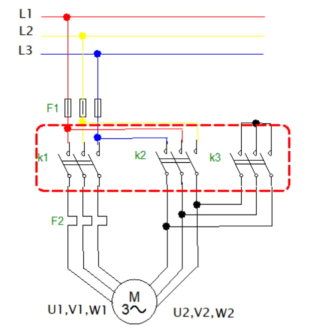
Figure 1. Circuit diagram of a typical star-delta motor starter. Image used courtesy of Simon Mugo
On starting the motor, contactors K1 and K2 are closed, converting the connection into a star configuration. On opening the time delay, K2 goes open while K3 closes hence converting the connection of the motor into a delta configuration. When connected, contactor K2 is closed, and this action applies phase voltage across the motor's terminals.
Calculating the Starting Current Reduction Obtained by Use of Star-Delta Motor Starter
Let’s evaluate the currents for the star and delta configurations.
Delta Connection
Figure 2 shows the voltages when the motor starter is configured in the delta configuration.
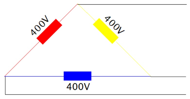
Figure 2. Delta connection. Image used courtesy of Simon Mugo
For the circuit delta connection, voltages are equated as follows:
$$V_{LINE} = V_{phase}$$
Therefore, the voltage supplied by the source is equivalent to the voltage that is measured across the delta windings. The current on the delta connection varies as shown by the equation below:
$$I_{LINE} = \sqrt{3} \cdot I_{phase}$$
Star Connection
Now, let's examine Figure 3, which illustrates the voltages when the motor starter is configured in the star configuration.
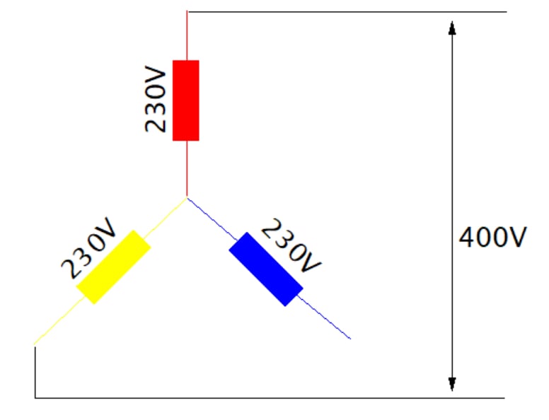
Figure 3. Star connection. Image used courtesy of Simon Mugo
For the star-connected part, the phase voltage is calculated as:
$$V_{phase} = \sqrt{3} \cdot V_{LINE}$$
If we rearrange the equation above, we get:
$$V_{LINE} = \frac{V_{phase}}{\sqrt{3}}$$
This means that the voltage measured across each star winding is (1/√3) times the voltage applied from the source. Here the currents of the line and the phase remain the same.
$$I_{LINE} = I_{phase}$$
Calculation Example of Star and Delta Currents
Consider a motor with an impedance winding of 10 Ω and with an applied voltage on the winding of 400 V. We can compare the currents for the star and delta connections.
For the delta connection:
$$V_{LINE} = V_{phase}$$
$$V_{LINE-delta} = V_{phase-delta} = 400 \text{ V}$$
The current is determined by:
$$I_{LINE} = \sqrt{3} \cdot I_{phase}$$
$$I_{LINE-delta} = \sqrt{3} \cdot \frac{V_{phase-delta}}{\text{Winding Impedance}} = \sqrt{3} \cdot \frac{400}{10} = 69.3 \text{ A}$$
For the star configuration:
$$V_{LINE-star} = \frac{V_{phase}}{\sqrt{3}}$$
$$V_{LINE-star} = \frac{400}{\sqrt{3}} = 230.9 \text{ V}$$
$$I_{LINE-star} = \frac{230}{10} = 23.1 \text{ A}$$
$$I_{LINE-star} = I_{phase-star} = 23.1 \text{ A}$$
We can compare these two calculated line current values:
$$\frac{I_{LINE-delta}}{I_{LINE-star}} = \frac{69.3}{23.1} = 3 $$
This means that
$$V_{LINE-delta} = 3 \cdot I_{LINE-star}$$
The calculation confirms the starting current is reduced using the star configuration. The star configuration current is one-third of the delta configuration current.
Control Circuit for a Star-Delta Motor Starter
The function of the control circuit is to switch contactors and control the star to delta configuration transition. A typical control circuit, as illustrated in Figure 4, comprises fuses, stop S0 and start S1 pushbutton switches, overload relays, star-delta timer K4, and magnetic contactors.
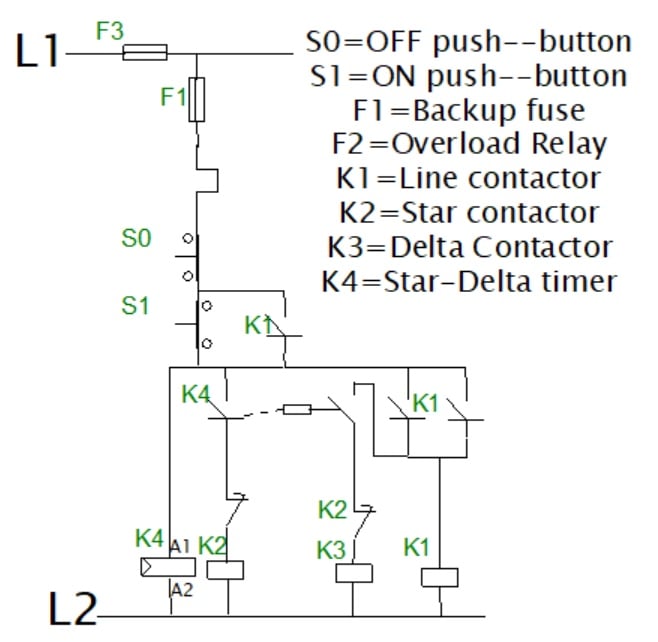
Figure 4. The control circuit for the star-delta starter. Image used courtesy of Simon Mugo
When you press S1, the coil of timer K4 starts and energizes the contactor K2 coil, which in turn energizes the contactor K1 coil. This starts the motor using the start configuration. The SI is wired parallel with the NO contact of conductor K1 in that the circuit will remain in latch condition until pressing S0.
After setting the duration of time on the circuit’s star-delta timer, de-energization of K2 takes place, and the motor runs in the configured delta system. Anytime you press S0, or when the system faces overload challenges, or anytime F1 blows out, the contactor K1 and K3 coils de-energize. The action stops the motor.
The star and delta contactors cannot close simultaneously due to interlocking them by incorporating NC contacts.
The transition of the motor circuit from star to delta can be through an open or a closed transition.
Open Transition
Here, the motor undergoes disconnection while transiting from star to delta. This means the starter disconnects momentarily from the electric motor and reconnects to the delta configuration. Figure 1 represents the open transition circuit. The stages of the open transition are off, star, transition, and delta stages in that order.
Closed Transition
Here, the motor is not disconnected from the circuit during the transition process from start to delta configuration.
Advantages and Disadvantages of the Star-Delta Starter
The star-delta starter has both advantages and disadvantages.
Advantages
- The components to set up the circuit are cheaply available relative to VFDs
- Reduced starting current by 33% of what the direct online starting consumes, meaning it is economical in terms of electricity consumption
- Better torque than other methods as it manipulates between star and delta configurations
- No heat production in open transition
- Overload relay size can be reduced to about 50% because it operates under low starting voltage and currents
- Voltage reduction devices are not required
Disadvantages
- Motors of six terminals are required, and this means a more expensive motor as compared to the DOL, which requires a simple three-terminal motor
- Larger cables are required, which means that to implement the system, more must be spent on the cable size
Applications of the Star-Delta Starter
Here are few examples of power electronics and systems where star-delta starters can be used:
- The star-delta starter is used for applications that are limited such as small fluid pumps with 7.5 HP used in grinding mills. This is reasonable where a heavy in-rush of electric current is not allowed because it has poor regulation.
- Modern industries are using star-delta starters to save energy because they can choose between the star and the delta configuration as per the required torque.
Key Takeaways for Star-Delta Motor Starters
- Star-delta motor starters comprise contactors, overload protection relays, circuit breakers, star and delta-configured contactors, and timers.
- The timer, the star, and the delta configuration differentiate this type of starter from the DOL starters.
- The power circuit of the start-delta starter begins at the three-phase power supply and then through both the start and delta configuration into the motor through the thermal overload protection relay.
- The control circuit taps both line 1 and line 2 power but leaves line 3.
- Two methods are involved in the transition of the motor from star to delta: open and closed.


