Facebook
 Google
 GitHub
 Linkedin
National Electrical Code Basics: Computing Voltage Drop in Branch Circuits and Feeders Part 1
Learn about voltage drops and how to calculate them in branch circuits and feeders.
To catch up on the rest of Lorenzo Mari's series on computing voltage drop in branch circuits and feeders, follow these links:
- National Electrical Code Basics: Computing Voltage Drop in Branch Circuits and Feeders Part 2
- National Electrical Code Basics: Computing Voltage Drop in Branch Circuits and Feeders Part 3
The wires utilized in electrical installations should be suitable to carry the current and avoid excessive voltage drop. With a few exceptions, the NEC does not have requirements on voltage drop because it’s not considered unsafe. Yet, it wastes power, and it is up to you to examine it.

Image used courtesy of Pixabay
What is a Voltage Drop?
Let’s go back to basics recalling Kirchhoff’s voltage law (KVL), which states that “the algebraic sum of voltage drops around a closed path is zero.” KVL follows the more general physical principle that potential differences along a closed path in any conservative energy field must sum to zero.
Figure 1 shows voltages around a closed path.
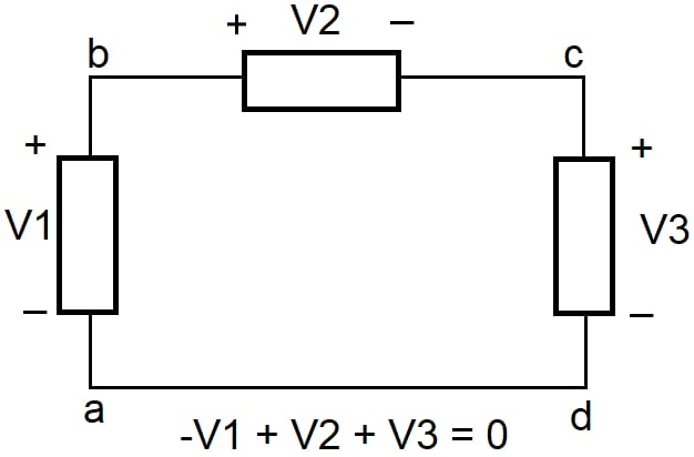
Figure 1. Voltages around a closed path. Image used courtesy of Lorenzo Mari
Taking the sign for each voltage as positive when going from + to – (higher to lower potential) and negative when going from – to + (lower to higher potential) in crossing the element and following the closed path abcda, we have
-V1 + V2+ V3 = 0
We see that all voltages are drops and added to zero. Yet, V1 is a negative voltage drop or positive voltage rise.
Another way of stating the above equation is
V2 + V3 = V1 or,
the sum of voltage drops equals the sum of voltage rises along any closed path.
V1 in figure 1 is a potential rise on the circuit, whereas V2 and V3 are potential drops or voltage drops.
Assuming that V1 is the source voltage, V2 is the voltage drop of a branch circuit or feeder conductor, and V3 is the voltage drop in the load, we’ll focus on V2.
The Rationale for Keeping a Low Voltage Drop
The primary purposes of voltage drop calculations are:
- Confirm that the voltage at the load allows a proper operation.
Electrical equipment operates most efficiently at its rated voltage. An electric motor drops power output by about 10% when below 5% rated voltage and around 19% when below 10% rated voltage. An incandescent lamp drops the light approximately 16% with a voltage 5% below rated and about 30% when 10% below rated. A fluorescent lamp might not operate at all under a high voltage drop.
- Attain an acceptable copper loss (heat dissipation in conductors).
Voltage Drops Recommended by NEC
Section 210.19(A) – branch circuits – Informational Note N° 3 recommends the voltage drop at the farthest outlet of power, heating, and lighting, or combination of such loads, to 3% of the applied voltage. Alternatively, the maximum combined voltage drop on the feeder and branch circuits to the farthest outlet should be 5%.
Section 215.2(A)(1) – feeders – Informational Note N° 2 have the same recommendations for feeders.
Those statements mean that the feeder could have a 1% voltage drop if the branch circuit had no more than 4%. Also, limiting the branch circuit voltage drop to 3% will allow a 2% drop in the feeder. These or any other combinations of feeder and branch circuit voltage drops not exceeding a total of 5% are adequate.
Section 647.3 permits the use of separately derived 120 V, 3-wire, single-phase systems with 60 V between each ungrounded conductor and the equipment grounding conductor, to reduce noise in sensitive electronic equipment locations, in commercial or industrial occupancies only.
Section 647.4(D) limits the voltage drop on any branch circuit serving sensitive electronic equipment to 1.5% of the applied voltage. Alternatively, it restricts feeder and branch-circuit conductors’ maximum combined voltage drop to 2.5%.
Sections 647(D)(1) and (2) give further details regarding voltage drops for fixed equipment and cord-connected equipment.
The voltage drop requirements for sensitive electronic equipment are not informational notes but mandatory.
Sound Voltage Drops
Typical voltage drop figures are 2% for the branch circuits plus 1% to 2% for feeders. The maximum branch-circuit voltage drop will be 2.4 V in a 120 V system and 4.8 V in a 240 V system.
While it is valid to use N° 14 AWG conductors in branch circuits, a minimum of N° 12 AWG is typical in residential occupancies, particularly in long runs. Section 210.11(C) requires 20A branch circuits for small appliances, laundry, bathroom, and garage. This practice arises from the increasing use of electricity in dwellings.
In commercial and industrial occupancies, the N° 12 AWG minimum is regularly crucial to avoid undue voltage drops.
Ohm’s Law Method to Calculate Voltage Drops
Several methods calculate single-phase and three-phase voltage drops, going from basic approximations to exact or actual values – the technique used and the level of detail depend on the required accuracy. Approximation methods are acceptable for routine use in residential, commercial, and industrial occupancies.
Ohm’s law method is one straightforward approach to obtaining approximate results. A small basic handheld calculator made all computations in the following examples.
Every conversion of energy can be related to the equation
Effect = cause/opposition
In electric circuits, Ohm’s law I(Ampere) = V(Volt)/R(Ohm) reflects this principle.
The following examples apply Ohm’s law in single-phase circuits, assuming a load power factor of 100% and negligible conductor reactance unless otherwise specified. They use direct-current analysis methods.
The figures of conductor resistance come from the NEC Table 8, under the column Direct-Current Resistance at 75°C.
Example 1:
Consider the series circuit shown in figure 2, where R1 represents the resistance of a branch-circuit conductor, and R2 characterizes the load resistance.
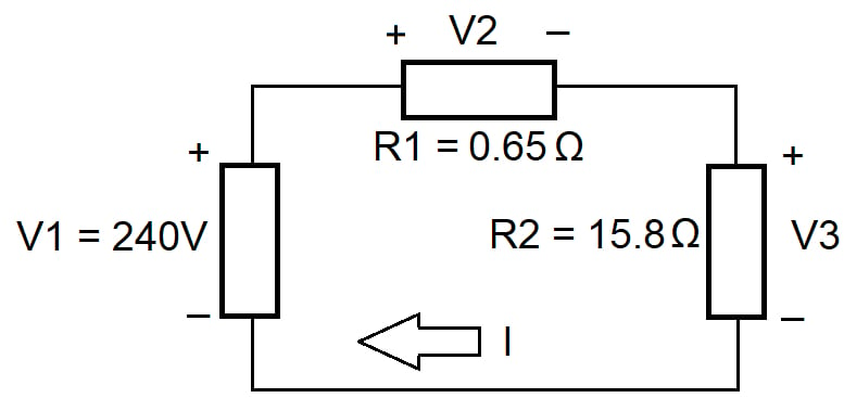
Figure 2. A series circuit. Image used courtesy of Lorenzo Mari
a. Find Rt.
Rt = R1 + R2 = 0.65 Ω + 15.8 Ω = 16.45 Ω.
b. Find I.
I=V/Rt = 240 V/16.45 Ω = 14.59 A.
c. Find V2 and V3.
V2 = IR1 = 14.59 A x 0.65 Ω = 9.48 V (branch-circuit voltage drop)
V3 = IR2 = 14.59 A x 15.8 Ω = 230.52 V.
d. Find the power dissipated by the resistors.
P1 = V2²/R1 = 9.48²/0.65 = 138.26 W (copper loss).
P2 = V3²/R2 = 230.52²/15.8 = 3 363.26 W.
e. Find the power output of the source and compare it with that dissipated by the resistors.
Psource = V x I = 240 V x 14.59 A = 3 501.60 W.
P(R1+R2) = 3 501.52 W.
The powers check. The slight difference is a rounding error.
f. Find the branch-circuit voltage drop in percentage.
(9.48 V/240 V) x 100 = 3.95%.
The Formula for Ohm’s Law Method
The Ohm’s law method to compute voltage drop may employ the following formula
VD = 2 x I x R x L
where
VD = Voltage drop (V) in conductors.
I = Current (A).
R = Conductor resistance (or impedance in AC circuits) in Ω/km.
L = Conductor length, in meters, from the source to the load divided by 1 000.
The number 2 reflects the return conductor from the load to the source.
The Benefits of Higher Voltages
Example 2:
Figure 3 shows a branch circuit conductor supplying a constant 3.36 kW load at a distance of 60 m. There are two voltage options for the source: 240 V or 120 V. Calculate the conductor size for a 3% maximum voltage drop.
NEC Table 8 shows a direct-current resistance of 1.01 Ω/km for conductor size N°4 AWG.
One-way resistance: 1.01 Ω/km x 0.060 km = 0.0606 Ω.
Current at 240 V: 3.36 kW/240 V = 14 A.
Current at 120 V: 3.36 kW/120 V = 28 A.
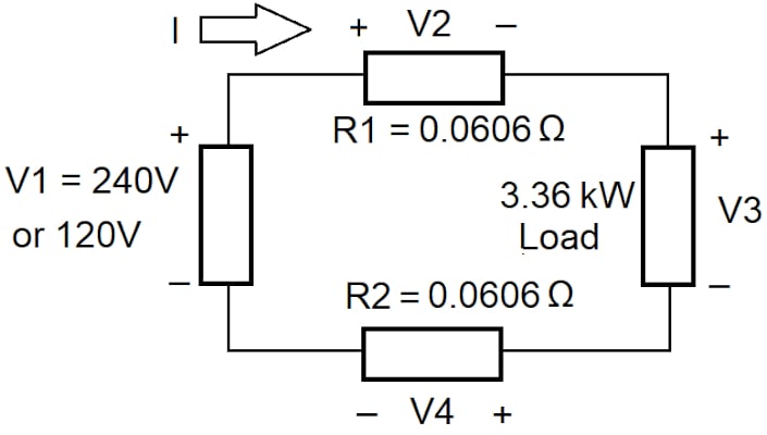
Figure 3. A branch-circuit conductor supplies constant power. Image used courtesy of Lorenzo Mari
VD1 = 2 x 14 A x 1.01 Ω/km x 0.060 km = 1.70 V = 0.71%.
VD2 = 2 x 28 A x 1.01 Ω/km x 0.060 km = 3.39 V = 2.83%.
Table 1 summarizes the conductor voltage drops in volts and percentages.
| Option | Source Voltage (V) | Power (kW) | Current (A) | Drop (V) | Drop (%) | Drop2 (V)/Drop1 (V) | Drop2 (%)/Drop1 (%) |
| 1 | 240 | 3.36 | 14 | 1.70 | 0.71 | 2 | 4 |
| 2 | 120 | 3.36 | 28 | 3.39 | 2.83 |
Table 1. Voltage drops with conductor N° 4 AWG. Image used courtesy of Lorenzo Mari
Both voltages satisfy the required voltage drop percentage using conductor N° 4 AWG.
Note that the voltage drop, measured in volts, in a 120 V system doubles that on a 240 V for the same load, distance, and conductor size. Yet, the voltage drop measured in percentage in a 120 V system is four times that on a 240 V.
These results reveal that 240 V may carry the same amount of power four times farther than 120 V, using the same conductor size and for the same voltage drop in percentage.
Table 1 shows room for a smaller conductor size in 240 V. NEC Table 8 displays a DC resistance of 3.984 Ω/km for a solid conductor size N°10 AWG.
VD = 2 x 14 A x 3.984 Ω/km x 0.060 km = 6.69 V = 2.79%.
The voltage drop is lower than 3%, as required.
Table 2 summarizes the conductor voltage drop in volts and percentage.
| SourceVoltage (V) | Power (kW) | Current (A) | Drop (V) | Drop (%) |
| 240 | 3.36 | 14 | 6.69 | 2.79 |
Table 2. Voltage drop with conductor N° 10 AWG. Image used courtesy of Lorenzo Mari
Higher voltages permit the use of smaller conductors, significantly saving construction costs.
Copper Losses
Voltage drops are wasted electric energy – in the form of heat – in the circuit conductors. Mathematically, the copper loss is a simple I²R, or V²/R, expressed in watts. The minor differences obtained using both expressions in these examples are rounding errors.
Total conductor length: 2 x 60 m = 120 m = 0.12 km.
Total N° 4 AWG conductor resistance: 1.01 Ω/km x 0.12 km = 0.1212 Ω.
Total N° 10 AWG conductor resistance: 3.984 Ω/km x 0.12 km = 0.4781 Ω.
Table 3 compares the copper loss in the arrangements analyzed in example 2.
| Arrangement | Source Voltage (V) | Conductor Size (AWG) | Current (A) | Drop (V) | Drop (%) | Conductor Resistance (Ω) | Copper Loss I²R(W) |
| 1 | 240 | 4 | 14 | 1.70 | 0.71 | 0.1212 | 23.75 |
| 2 | 120 | 4 | 28 | 3.39 | 2.83 | 0.1212 | 95.02 |
| 3 | 240 | 10 | 14 | 6.69 | 2.79 | 0.4781 | 93.71 |
Table 3. Comparison of copper losses in the arrangements of example 2. Image used courtesy of Lorenzo Mari
A comparison of arrangements 1 and 2 shows the close relationship between voltage drop and copper loss. Arrangement 1 will waste less energy during the circuit’s life – just by increasing the voltage.
Although arrangement 1 has the lowest copper loss, it employs a large conductor size, increasing material and labor costs. Note that arrangement 3 uses a smaller conductor size – economically advantageous – while complying with the voltage drop specification and a copper loss similar to arrangement 2, making it the best choice.
Example 3:
Repeat example 2 for a source voltage of 240Vac, assuming a load power factor of 0.85. 2 conductors N° 10 AWG in PVC conduit.
Let’s use NEC Table 9 and modify the formula to
VD = 2 x I x Z x L
to consider the effective impedance of the circuit.
Effective Z at 0.85 PF column in PVC conduit = 3.60 Ω/km.
VD = 2 x 14 A x 3.60 Ω/km x 0.06 km = 6.05 V = 2.52 %.
Compare these results with Table 2.
Conclusions
Most voltage drops mentioned by the National Electrical Code are recommendations. Beware that figures in some sections are requirements.
Voltage drop must be as low as possible, balancing technical and economic factors.
Where significant distance and power are involved, it is advantageous to use higher voltages to reduce conductor size and copper loss.
Approximate voltage drop calculations are frequently acceptable. However, it is essential to understand the fundamental limitations of different types of voltage drop computation procedures.
Feature image used courtesy of Pixabay
Related Content