Facebook
 Google
 GitHub
 Linkedin
Selecting Motor Controllers
Learn how to select the right motor controller for your application.
NEC’s Article 100, “Definitions,” defines a motor controller as any switch or device typically employed for motor start and stop by making and breaking the circuit current.
As employed in Part VII of NEC Article 430, the term “controller” comprises any switch or device commonly used to start and stop a motor, including motor starters and controllers – the contactor mechanism.
NEC Article 430. Part VII Motor Controllers
NEC Section 430.81 General
Part VII mandates the use of appropriate motor controllers for all motors.
Figure 1 shows the location of the motor controller in a motor branch circuit.
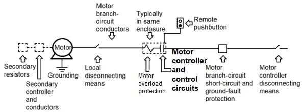
Figure 1. Location for the motor controller in a motor branch circuit. Image used courtesy of Lorenzo Mari
Section 430.81(A) Stationary Motor of 1/8 hp or Less
- This type of motor may use the branch-circuit disconnecting means as the motor controller. The motors must be mounted stationary, running permanently, and constructed so they cannot be damaged by overload or failure to start. Examples are clock motors and similar devices.
Section 430.109(B) permits the branch-circuit overcurrent device to act as the disconnecting means for stationary motors of 1/8 hp or less. For instance, branch-circuit fuses or circuit breakers are acceptable control devices for this motor type if the winding impedance is high enough to prevent damage with the rotor overloaded or continuously at a standstill.
Figure 2 shows a stationary motor of 1/8 hp or less supplied from a panelboard, where the overcurrent protective device (OCPD) acts as the motor controller.

Figure 2. Power supply to a stationary motor 1/8 hp or less. Image used courtesy of Lorenzo Mari
Section 430.81(B) Portable Motor of 1/3 hp or Less
- This type of motor may use an attachment plug and receptacle or cord connector as the motor controller.
An attachment plug is the component of a cord that connects to an outlet or another device to establish an electrical circuit.
Figure 3 shows a portable motor plugged into a receptacle.
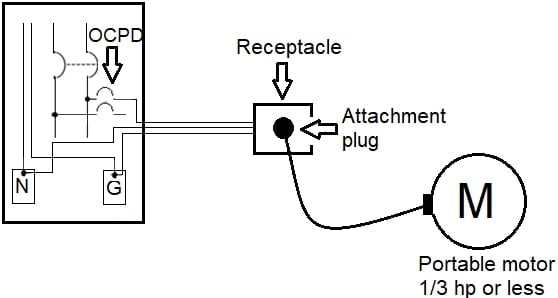
Figure 3. Power supply to a portable motor 1/3 hp or less. Image used courtesy of Lorenzo Mari
Although electric clocks were cited as examples in Section 430.81(A), Figure 4 depicts a clock that does not fall under that section because it has a plug-and-cord connection, making it portable. Since it may use the plug-and-cord connection as a motor controller and has a power under 1/3 hp, it falls into Section 430.81(B).
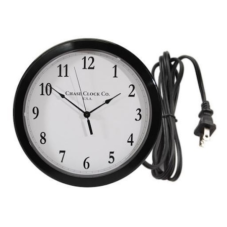
Figure 4. An electric clock with a plug and cord. Image used courtesy of ClockParts.com
NEC Section 430.82 Motor Controller Design
Section 430.82(A)Starting and Stopping
- A motor controller must be able to start and stop the motor it controls and interrupt its locked-rotor current.
In addition to starting and stopping the motor it controls, an AC controller must be able to interrupt the stalled rotor current. The magnitude of the stalled-rotor current is several times larger than the running current, and damage may result to the controller unless it can interrupt such current.
Section 430.82(B) Autotransformer
- Provide an off position, a running position, and at least one starting position in an autotransformer starter.
- The autotransformer starter must not rest in the starting position or any position that disables the circuit's overload device.
Autotransformer starting is an effective reduced voltage starting method with lessened transient problems and several advantages over star-delta starting.
The starting sequence involves taps in the autotransformer, which supply the reduced voltage.
Section 430.82(C) Rheostats
- Design the motor-starting rheostats so the contact arm cannot be on intermediate segments. When in the starting position, the point or plate on which the armrests must not have an electrical connection with the resistor.
- Provide motor-starting rheostats for DC motors operated from a constant voltage supply. Automatic devices interrupt the supply before the motor’s speed falls to less than one-third of its expected value.
Rheostats are used to adjust the electrical resistance in a circuit. They reduce the supply voltage to the stator of an induction motor when starting by adding resistances to each phase of the stator winding. Initially, the resistances are set to their maximum value, causing a significant voltage drop. As the motor speeds up, the resistances are gradually reduced until the stator receives the rated voltage. At this point, the resistances are entirely removed from the circuit, placing the rheostat in the run position.
NEC Section 430.83 Ratings
The motor controller must have a rating per Section 430.83(A) unless otherwise permitted in sections 430.83(B) or (C) or under Section 430.83(D).
Section 430.83(A) General
Section 430.83(A)(1) Horsepower Ratings
- Motor controllers, other than inverse-time circuit breakers and molded-case switches, must have horsepower ratings at the application voltage equal to or higher than the motor’s horsepower rating.
Section 430.83(A)(2) Circuit Breaker
- Only a branch-circuit inverse-time circuit breaker rated in amperes can be used as a motor controller. When the circuit breaker also provides overload protection, it must adhere to the rules of Part III in this article.
Section 430.83(A)(3) Molded Case Switch
- A molded case switch rated in amperes can be used as a motor controller for all motors.
Molded case switches are rated in amperes and can be used up to 100% of their rating. They are on-off devices and need protection from a fuse or a circuit breaker of equal ampere rating because they have no thermal overload protection.
They do not contain a trip unit and may or may not be equipped with a fixed magnetic trip function – nonadjustable – designed to operate under high fault currents where immediate interruption of electric power is necessary – a self-protect device.
Molded-case switches may be used as motor disconnecting means per Section 430.109(A)(3) and as a motor disconnecting means and motor controller per Section 430.111.
Molded-case circuit breakers are equipped with either a thermal-magnetic or an electronic trip unit.
Figure 5 shows a molded-case switch rated 800 A.
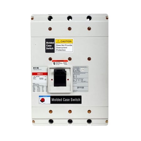
Figure 5. A molded-case switch. Image used courtesy of EATON
Section 430.83(B) Small Motors
- Devices complying with sections 430.81(A) and (B) may be employed as motor controllers.
Section 430.83(C) Stationary Motors of 2 Horsepower or Less.
- The motor controller of stationary motors up to 2 hp, rated 300 V or less, may be any of the following:
◦ A general-use switch with an ampere rating not less than double the motor’s full-load current.
◦ On AC circuits, an AC general-use snap switch, but not a general-use AC/DC snap switch, assures the motor full load current rating does not exceed 80% of the switch’s current rating.
Snap switches can safely control motors with a 2 hp or less rating – section 404 .9 covers general-use snap switches.
Figure 6 shows a general-use snap-switch installed as a motor controller.
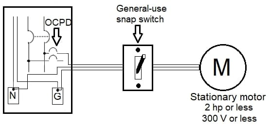
Figure 6. General-use snap-switch used as motor controller. Image used courtesy of Lorenzo Mari
Section 430.83(D) Torque Motors
- The motor controller must have a continuous-duty, full-load current rating that is at least equal to the full-load rating marked on the motor’s nameplate.
- For a motor controller rated in horsepower and not marked or rated as covered above, establish the equivalent current rating from the horsepower rating employing tables 430.147 through 430.150.
Section 430.83(E) Voltage Rating
- Apply controllers with a straight voltage rating in circuits where the voltage between conductors does not exceed the voltage rating.
- Apply controllers with a slash rating only in solidly grounded circuits in which the voltage to ground from any conductor does not exceed the lower value of the voltage rating and the voltage between two conductors does not exceed the higher value of the voltage rating.
Section 430.83(F) Short-Circuit Current Rating
- Do not install a controller where the available fault current surpasses its short-circuit current rating.
NEC Section 430.84 Need Not Open All Conductors
- The controller does not need to open all the conductors to the motor, but only those required to start and stop it.
Exception: When the controller also serves as the disconnecting means, it must open all the ungrounded conductors to the motor per Section 430.111.
The controller must only interrupt enough conductors to start and stop the motor.
For example, a 2-pole starter of suitable horsepower rating could be utilized for a 3-phase motor, providing overload protection in all three ungrounded conductors with protective devices separate from the starter – such as dual-element, time-delay fuses, which may provide overload and short-circuit protection for the motor branch circuit.
Figure 7 shows a 2-pole contactor making and breaking only two conductors in a 3-phase system.
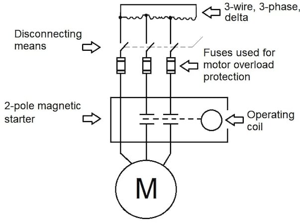
Figure 7. 2-pole magnetic starter opening only two conductors of the motor supply circuit. Image used courtesy of Lorenzo Mari
In the same way, only one conductor may be opened for DC or single-phase motor circuits.
NEC Section 430.85 In Grounded Conductor
- Suppose the controller is designed so all ungrounded conductors shall be simultaneously opened, if the grounded conductor is opened, one pole of the controller may be placed in a permanently grounded conductor.
This rule permits using a 3-pole switch, circuit breaker, or motor starter in a 3-phase motor circuit derived from a 3-phase, 3-wire, corner-grounded delta system (see Figure 8).
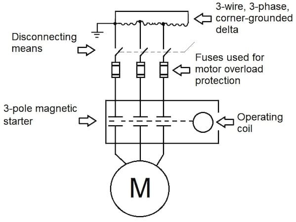
Figure 8. 3-pole magnetic starter opening a 3-wire circuit with one conductor grounded. Image used courtesy of Lorenzo Mari
Another example is 120-V circuits, where, typically, one conductor is grounded. A 2-pole controller is permitted for this type of circuit if it opens both conductors simultaneously.
NEC Section 430.87 Number of Motors Served by Each Controller
- The general rule is that each motor must have an individual motor controller.
Exception N° 1: This exception permits a single controller rated at not less than the equivalent horsepower of all the motors in a group – as determined under Section 430.110(C)(1) – to serve the group under any of the following conditions:
1. Several motors propel parts of a single machine or piece of apparatus.
2. One overcurrent device protects the group of motors as permitted in Section 430.53(A).
3. A single room contains a group of motors within sight of the controller location.
This exception applies to motors rated 1 kV or less only.
Section 430.110(C)(1) considers all motors’ combined full-load current and locked-rotor current as a single motor for calculation purposes.
Section 430.53(A) applies to several motors, each not exceeding 1 hp. Condition 2 does not apply to several motors on a single branch circuit under sections 430.53(B) and 430.53(C). Using a single controller for higher hp ratings applies only if the group of motors satisfies conditions 1 or 3.
These conditions are similar to those in the exception in Section 430.112, for a single disconnecting means serving a group of motors.
Exception N° 2: This exception permits a branch-circuit disconnecting means to operate several motors as the controller per Section 430.81(A).
NEC Section 430.88 Adjustable-Speed Motors
- Equip and connect adjustable-speed motors controlled through field regulation to avoid starting under a weakened field.
Exception: This exception allows the motor to start under a weakened field if designed for such starting.
Shunt and compound-wound DC motors have speed variations controlled by regulating the field current. Starting a motor with a weakened field is dangerous because the starting current would be excessive, causing the armature to burn out unless the motor is designed for starting in this way.
NEC Section 430.89 Speed Limitation
Provide the following types of machines with speed-limiting devices or other speed limiting-means:
◦ Separately excited DC motors
◦ Series motors
◦ Motor-generators and converters
Exception: There is no need to provide separate speed-limiting devices or means
under either of the following conditions:
- If the intrinsic characteristics of the machines, the system, the load, and the mechanical connection will effectively limit the speed.
- If the machine is always manually controlled by a qualified operator.
One method to prevent overspeed is a centrifugal device on the machine’s shaft. This device must be set up to activate a contact at a predetermined speed, triggering a circuit breaker and gradually stopping the machine.
NEC Section 430.90 Combination Fuseholder and Switch as Controller.
- When using a combination fuse holder and switch as a motor controller, the fuse holder must only permit the size of the fuse specified in Part III of this article, which covers overload protection.
Exception: Fuseholders smaller than those covered in Part III of this article will be allowed when using time-delay fuses suitable for the motor-starting characteristics.
Selecting Suitable Motor Controllers Takeaways
- Part VII of Article 430 applies to motor controllers for all motors.
- A motor controller must be able to start and stop the motor it controls and interrupt the locked-rotor current.
- Stationary motors not greater than 1/8 hp may use the branch-circuit disconnecting means as the motor controller.
- An attachment plug, receptacle, or cord connector may be used as a motor controller for portable motors of 1/3 hp or less.
- An AC general-use snap switch may be the motor controller of a stationary motor up to 2 hp, 300 V.
- Motor controllers must have horsepower ratings equal to or higher than the motor’s horsepower rating.
- Controllers do not need to open all the conductors to the motor.
Related Content