Facebook
 Google
 GitHub
 Linkedin
Protect Motor and Lighting Control Circuits in Certain Conditions
Learn how to protect motor and lighting control circuits from overcurrent.
NEC’s Article 100, “Definitions,” defines a control circuit as the circuit of a control apparatus or system that transmits the electric signals directing the controller’s performance but does not carry the primary power current.
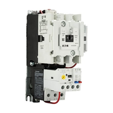
Image used courtesy of EATON
In practical terms, Part VI of Article 430 considers the load of a control circuit the magnetic motor starter’s operating coil, a magnetic contactor, or a relay operating one or several additional circuits.
NEC Article 430. Part VI Motor Control Circuits
NEC Section 430.71 General
The provisions of Part VI apply to the particular conditions of motor control circuits and modify the general requirements.
A control circuit includes the conductors, raceway, contactor operating coil, power supply, protective devices, and switching devices to energize the operating coil.
Figure 1 shows the location of the motor control circuits in a motor branch circuit.
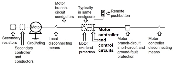
Figure 1. Location for the motor control circuits in a motor branch circuit. Image used courtesy of Lorenzo Mari
NEC Section 430.72 Overcurrent Protection
Section 430.72(A) General
This section explains how to protect the operating coil circuit of a magnetic motor starter, as distinct from a manually operated starter.
Protect a control circuit tapped from the load side of a motor branch circuit short-circuit and ground-fault protective device(s)—operating to control the motor(s) connected to that branch circuit—against overcurrent, per Section 430.72.
This rule covers the motor control circuits derived inside a motor starter from the power circuit, which connects to the starter’s line terminals. The circuit starts at the fuses or circuit breaker, which provides branch-circuit protection for the conductors supplying the starter.
- Do not consider the tapped motor control circuit as a branch circuit. Protect it with a supplementary or branch-circuit overcurrent protective device.
As per the rule, the branch-circuit protective device before the starter or supplementary protection inside the starter enclosure may protect the control-circuit conductors.
- Protect a motor control circuit other than a tapped control circuit against overcurrent per Section 724.43 of the notes to NEC tables 11(A) and 11(B) in Chapter 9, as applicable.
These separate control circuits originate from a panelboard or a control transformer to deliver lower voltage control to starters that supply higher voltage motors – for example, a 120-V circuit controlling a 460-V motor in a 480-V branch circuit.
There are three classes of remote control and signaling circuits depending on the power available in the circuit. The new Section 300.26 in the 2023 edition classifies them as either power-limited or non-power-limited, conforming to the following:
- Class 1: power-limited circuits complying with Section 724.3.
- Class 2 and Class 3: power-limited circuits complying with Section 725.3.
- Non-power-limited circuits: installed per sections 300.2 through 300.25.
Motor controllers typically operate using Class 1 non-power-limited remote-control circuits, as per Section 725.41(B) in NEC’s 2020 edition.
Class 2 and 3 control circuits have low energy-handling ability; the relatively high energy required for operating coils causes most control circuits for magnetic starters and contactors not to qualify as Class 2 or 3 circuits.
NEC’s 2023 edition has a new Article 724 that covers only Class 1 power-limited circuits and provides the same basic information previously covered in parts I and II of the former Article 725 for power-limited circuits.
Sections 300.2 through 300.25 in NEC’s 2023 edition do not include data to install Class 1 non-power-limited circuits.
The NFPA Standards Council issued a tentative interim amendment (TIA) Number 23-8 (TIA Log #1688) for the 2023 National Electrical Code on March 21st, 2023, effective April 10th, 2023. This TIA intended to revise Section 300.26 to include non-power-limited remote-control and signaling circuits.
The NFPA Standards Council Decision (Final) D#23-4 was to uphold the appeal.
The revised Section 300.26(C) of the 2023 edition covers non-power-limited remote-control and signaling circuits.
Please refer to NFPA 70 for more information.
Section 724.43 states that overcurrent protection for conductors 14 AWG and larger must comply with the conductor ampacity without applying the ampacity adjustment and correction factors specified in Section 310.15 to the ampacity calculation.
In other words, Section 724.43 states that overcurrent protection for conductors 14 AWG and larger must comply with the conductor ampacities from tables 310.16 through 310.21.
Overcurrent protection must not exceed 7 A for 18 AWG conductors and 10 A for 16 AWG conductors.
Exception: Where other articles of this Code permit or require other overcurrent protection.
The new Section 300.26(C)(3) “Overcurrent Protection,” specifies the following:
(a) Overcurrent protection for conductors 14 AWG copper and larger shall be provided per the conductor ampacity without applying the ampacity adjustment and correction factors specified in Section 310.15 to the ampacity calculation.
Note that there is no need to derate the ampacity of the control wires.
(b) Overcurrent protection shall not exceed 7 A for 18 AWG copper conductors and 10 A for 16 AWG copper and 14 AWG copper-clad aluminum.
These amperage values correspond to sections 240.4(D)(1), (2), and (3) regarding small conductors.
Exception: The overcurrent protection specified in sections 300.26(C)(3)(1) and 300.26(C)(3)(2) shall not be required where this Code requires or permits other overcurrent protection ratings.
Although Section 740.43 pertains to power-limited circuits and Section 300.26(C)(3) pertains to non-power-limited circuits, both rules are similar.
Section 430.72(B) Conductor Protection
- Provide overcurrent protection for conductors per sections 430.72(B)(1) or (2).
Exception N° 1:
- The conductors of control circuits require only short-circuit and ground-fault protection when its opening would create a hazard, e.g., the control circuit of a fire pump motor.
- The motor branch-circuit short-circuit and ground-fault protective apparatus are allowed to protect the control circuit conductors.
Exception N° 2:
- The overcurrent protection on the primary side of a transformer supplying control conductors may protect such conductors if the transformer is single-phase and has only a two-wire, single-voltage secondary. The overcurrent protection must not exceed the value obtained by multiplying the appropriate maximum rating of the overcurrent device for the secondary conductor, as provided in Table 430.72(B)(2), by the secondary-to-primary voltage ratio.
- The overcurrent protection on the primary side of a transformer does not protect the transformer’s secondary conductors if they are other than two-wire.
Section 430.72(B)(1) Separate Overcurrent Protection
- Provide a separate overcurrent protection when the motor branch-circuit short-circuit and ground-fault protective device(s) do not give protection per Section 430.72(B)(2).
- The overcurrent protection must not exceed the values provided by Column A of Table 430.72(B)(2).
Note that the values in column A, for sizes No. 14 AWG or larger, correspond to the quantities indicated in table 310.16 through 310.21, as applicable. The values for sizes N° 16 AWG and N° 18 AWG adhere to the rules in Section 724.43 and the new Section 300.26(C)(3)(b).
Section 430.72(B)(2) Branch-Circuit Overcurrent Protective Device
- Protecting the conductors through the motor branch-circuit short-circuit and ground-fault protective device is acceptable, but only short-circuit and ground-fault protection is required.
- When the conductors do not extend beyond the motor control equipment enclosure, the protective device(s) rating must not exceed the value specified in Column B of NEC Table 430.72(B)(2).
One example of this condition is factory-installed control circuit wires connected to the start-stop buttons on the starter’s cover.
Note that the values in column B, for sizes No. 14 AWG or larger, correspond to 400% of the values indicated in Table 310.17, 60°C column (Ampacities of single-insulated conductors in free air).
- When the conductors extend beyond the motor control equipment enclosure, the protective device(s) rating must not exceed the value specified in Column C of NEC Table 430.72(B)(2).
This rule applies to protecting control wires running from a starter to a remote-control device such as a pushbutton station, limit switch, float switch, or similar device.
Note that the values in column C, for sizes No. 14 AWG or larger, correspond to 300% of the values indicated in Table 310.16, 60°C column (Ampacities of insulated conductors with no more than three current-carrying conductors in raceway, cable, or earth). The values for sizes N° 16 AWG and N° 18 AWG adhere to the rules in Section 724.43 and the new Section 300.26(C)(3)(b).
Example 1: Figure 2 shows a motor circuit hookup for a magnetic starter.
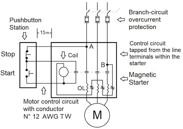
Figure 2. Setup for Example 1. Image used courtesy of Lorenzo Mari
a) Determine the maximum rating of the motor branch-circuit overcurrent protection, which is adequate for protecting N° 12 AWG TW remote-control circuit copper conductors running to a pushbutton station at a 15 m distance.
b) Find the rating of supplementary fuses to install in both remote-control circuit conductors (points A and B) if the rating of the motor branch-circuit protection exceeds the value computed in question a).
Solution:
a) Enter Table 430.72(B)(2) and read 60 A under Column C, N° 12 AWG copper conductor file.
The maximum rating of the overcurrent protection is 60 A.
b) Enter Table 310.16, the column of 60°C, copper conductors, and read an ampacity of 20 A for a conductor size N° 12 AWG.
The maximum rating of supplementary fuses is 20 A.
Example 2: A magnetic starter controls a motor whose branch-circuit overcurrent protection is a set of three 60-A fuses. The factory-installed start-stop buttons rest on the starter’s box cover. A visual inspection of the magnetic starter reveals that the internal coil circuit conductor size is N° 16 AWG copper.
a) Determine if the branch-circuit overcurrent protection is acceptable to protect the factory-installed coil-circuit wires.
b) If the answer to question a) is negative, find a solution to comply with NEC’s rules.
Solution:
a) Enter Table 430.72(B)(2) and read 40 A under Column B, N° 16 AWG copper conductor file.
As 60 A is higher than 40 A, branch-circuit overcurrent protection is unacceptable for protecting the coil-circuit wires.
b) Provide a separate protection within the starter, rated not greater than the value shown for the wire size in Column A of Table 430.72(B)(2).
Enter Table 430.72(B)(2) and read 10 A under Column A, N° 16 AWG copper conductor file.
One way to comply with NEC’s rules is to install a set of two 10-A fuses in the coil-circuit wires.
Many starters employ the small copper conductor sizes N° 18 AWG and N° 16 AWG for the coil circuits. When the coil conductors do not extend beyond the motor control equipment enclosure, Column B shows that separate coil-circuit protection is unnecessary when the branch-circuit protection is rated not over 25 A for N° 18 wires and up to 40 A for N° 16 wires.
According to Column C, there is no need for separate coil-circuit protection in situations where the coil conductors extend beyond the motor control equipment enclosure if the branch-circuit protection rating is no more than 7 A for N° 18 wires and no more than 10 A for N° 16 wires. In this case, branch-circuit fuses with a 7- or 10-A rating could eliminate separate protection within the starter.
The fuse rating of 7 A is not standard, but Section 240.6(A) permits the use of fuses with nonstandard ampere ratings.
Section 430.72(C) Control Circuit Transformer
There are high-voltage contactor coils for motor controllers. However, when safety requirements, atmospheric restrictions, and other working conditions exist, it is vital to consider control circuits with lower voltages to protect the operating personnel. For example, 120- or 240-V coil circuits can control 460-V motors in 480-V circuits. In these cases, control transformers step the voltage down, allowing the use of lower-voltage coil circuits.
- Protect motor control circuit transformers per sections 430.72(C)(1), (2), (3), (4), or (5).
Exception: Omit overcurrent protection when the opening of the control circuit would create a hazard, like the control circuit of a fire pump.
This exception excludes the need for control-circuit protection when its opening would be unacceptable, such as for essential systems or safety-related operations.
Figure 3 shows a control circuit supplied by a transformer within the starter enclosure.
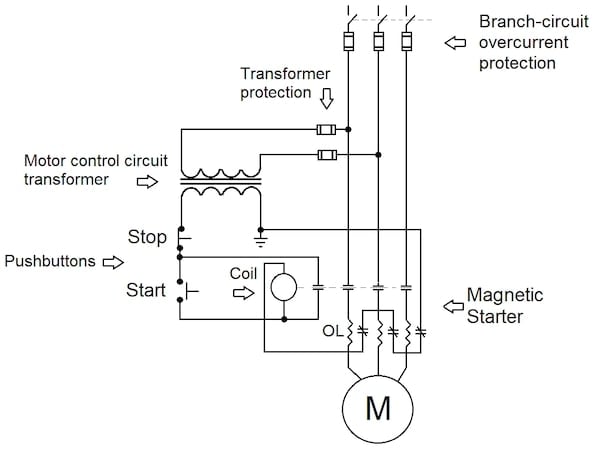
Figure 3. A control circuit supplied by a transformer. Image used courtesy of Lorenzo Mari
Section 430.72(C)(1) Class 1 Power-Limited, Class 2, or Class 3 Circuits
- A transformer's circuit supplying a Class 1 power-limited circuit must comply with sections 724.30 through 724.52. When providing a Class 2 or Class 3 remote-control circuit, it must comply with the rules in Part II of Article 725.
Section 430.72(C)(2) Transformers
- Protect the transformers per Section 450.3.
Section 450.3 covers transformer overcurrent protection. The rating or setting of the overcurrent protection is given in Table 450.3(A) for transformers over 1 kV and Table 450.3(B) for transformers of 1 kV or less. The tables include primary and secondary protection.
The exception N° 2 to Section 430.72(B) permits protecting the secondary conductors following the ampere values shown in Table 430.72(B)(2) for their particular sizes. Be sure to reflect these values on the primary side.
Also, see Section 240.4(F), “Protection of transformer secondary conductors.”
Section 430.72(C)(3) Less Than 50 VA
- It is acceptable to protect control circuit transformers rated less than 50 VA, integrated into the motor controller, and placed inside the enclosure, employing impedance limiting means, primary overcurrent devices, or other inherent protective means.
Section 430.72(C)(4) Primary Less Than 2 A
- Installing an overcurrent device rated or set at not more than 500% of the primary current when it is less than 2 A is acceptable for protecting the control circuit transformer.
The protective device must be placed in each ungrounded conductor supplying current to the transformer primary.
Example 3: Find the maximum rating for the transformer primary protection in Figure 3 if the primary rated current is 1.5 A, and pick a fuse for each ungrounded conductor.
Solution:
1.5 A x 500% = 7.5 A
Level to the next smaller size in Section 240.6(A) and use 6-A fuses since the maximum rating is 7.5 A.
Example 4: Assume that the control transformer in Example 3 has a voltage rating of 480/120 V, with the conductors placed inside the enclosure. Determine the minimum copper conductor size for the secondary conductors that the primary fuses will protect.
Solution:
Voltage ratio = 480 V/120 V = 4
6 A x 4 = 24 A
Enter Table 430.72(B)(2) and read 25 A under Column B, N° 18 AWG copper conductor file.
The minimum conductor size is N° 18 AWG.
You may prove this result by following the text to the letter in Exception 2 to Section 430.72(B) as follows:
Assume your hookup has a control transformer with copper conductors size N° 18 AWG in the secondary circuit.
Enter Table 430.72(B)(2) and read 25 A under Column B, N° 18 AWG copper conductor file.
Find the maximum rating allowed for the primary protection by multiplying 25 A by the secondary-to-primary voltage ratio.
25 A x (120 V / 480 V) = 6.25 A.
If the 6-A rating of the primary fuse is below the maximum value, it protects the secondary circuit.
Section 430.72(C)(5) Other Means
- It is permissible to protect through other approved methods.
Protecting a Lighting Contactor’s Coil Circuit
The following example pertains to lighting rather than electric motors. However, it is closely related to a motor scenario as the control circuit is also Class 1.
The new Section 724.45(C) addresses branch-circuit taps for lighting and power, requiring short-circuit and ground-fault protection only. You can provide this protection from the branch-circuit protective device as long as its rating does not exceed 300% of the circuit conductor’s ampacity.
Example 5: Figure 4 shows an arrangement with a magnetic contactor controlling a lighting load. The control circuit copper conductors, tapped from the branch circuit, are N° 14 AWG TW.
a) Determine the maximum rating of the branch-circuit fuses to consider the control-circuit conductors protected.
b) Determine the minimum copper conductor size required for the control circuit if the branch circuit fuses are rated 90 A.
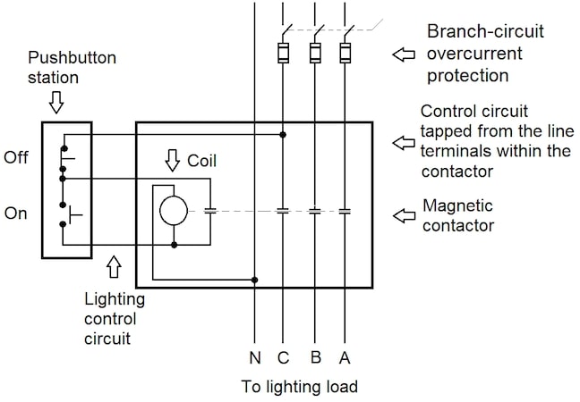
Figure 4. Hookup for Example 5. Image used courtesy of Lorenzo Mari
Solution:
Enter Table 310.16 and read 15 A under the 60°C Column, N° 14 AWG copper conductor file.
300% x 15 A = 45 A
The fuses' maximum rating is 45 A, the standard ampere rating per Table 240.6(A).
300% x minimum ampacity = 90 A
Minimum ampacity = 90 A / 3 = 30 A
Enter Table 310.16 and read 30 A under the 60°C Column, N° 10 AWG copper conductor file.
The minimum conductor size is N° 10 AWG TW
Protecting Motor and Lighting Control Circuits in Particular Conditions
- Part VI of Article 430 applies to the particular conditions of motor control circuits, modifying the general requirements.
- Branch-circuit protective devices or supplementary protection may protect the control-circuit conductors.
- There are three classes of remote control and signaling circuits.
- Typically, motor control circuits are Class 1 non-power-limited circuits.
- Control transformers step the voltage down, increasing the safety of operations personnel.
- The setup and functioning of motor starters and lighting contactors are similar.