Facebook
 Google
 GitHub
 Linkedin
Understanding Motor Control Centers
Learn about the NEC requirements for motor control centers.
The NEC Article 100, “Definitions,” defines a motor control center (MCC) as an assembly of one or more enclosed sections with a common power bus mainly containing motor control units.

Image used courtesy of Berg Elektrik
Motor control centers are essential electrical power distribution system components, enabling operators to start, stop, and monitor motors.
The design of each enclosed section manages and protects the electric motors in the system, allowing for centralized control of equipment and machinery.
The motor control units include starters, relays, contactors, and additional control components to operate the individual motors. A motor starter consists of a contactor and an overload relay.
Many construction requirements in Part VIII derive from Article 408, “Switchboards, switchgear, and panelboards,” since MCCs modify switchboards tailored to motor control functions.
NEC Article 430. Part VIII Motor Control Centers
NEC Section 430.92 General
Part VIII involves MCCs for controlling motors, lighting, and power circuits.
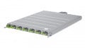
Figure 1 shows an MCC scheme.
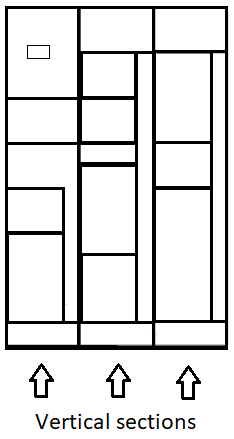
Figure 1. An MCC scheme. Image used courtesy of Lorenzo Mari
Figure 2 shows a conventional MCC.
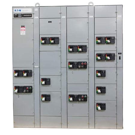
Figure 2. A conventional MCC. Image used courtesy of Eaton
NEC Section 430.94 Overcurrent Protection
- Follow Parts I, II, and VIII of Article 240 for the overcurrent protection of the MCCs.
- Do not exceed the common power bus ampere rating when selecting the ampere rating or setting of the overcurrent protective device.
When using an overcurrent protective device rated lower than the main bus, ensure it adequately carries the load calculated per Part II of this Article.
A typical MCC has two types of busses:
◦ A horizontal bus (common power bus) connects the primary power source to the vertical bus sections across the assembly's length.
◦ Vertical buses supply power to the individual units.
Figure 3 shows a typical MCC bus arrangement.
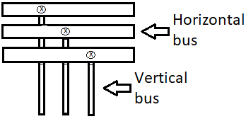
Figure 3. Buses in an MCC. Image used courtesy of Lorenzo Mari
- Locate the protection in one of the following places:
◦ An overcurrent protective device situated ahead of the MCC. See Figure 4.
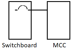
Figure 4. Overcurrent protective device ahead of the MCC. Image used courtesy of Lorenzo Mari
◦ A main overcurrent protective device positioned within the MCC. See Figure 5.
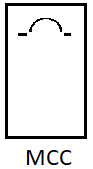
Figure 5. Overcurrent protective device located inside the MCC. Image used courtesy of Lorenzo Mari
NEC Section 430.95 Service Equipment
Provide a single main disconnecting means to disconnect all ungrounded service conductors when using the MCC as service equipment.
Exception N° 1: The NEC permits a second service disconnect if it is required to supply additional equipment.
Provide a main bonding jumper sized per section 250.28(D) when there is a grounded conductor. Place the main bonding jumper inside one of the sections and connect the grounded conductor on its supply side to the MCC ground bus.
Figure 6 shows a main bonding jumper connecting the grounded conductor to the MCC enclosure and ground bus.

Figure 6. Main bonding jumper in an MCC used as service equipment. Image used courtesy of Lorenzo Mari
Exception N° 2: It is permitted to connect high-impedance grounded neutral systems per Section 250.36.
NEC Section 430.96 Grounding
- Bond all sections of an MCC with a conductor or bus sized per Table 250.122. Connect all equipment grounding conductors to this conductor or bus or a grounding termination point available in a single-section MCC.
The use of a grounding bus is usual in these applications.
NEC Section 430.97 Busbars and Conductors
Section 430.97(A) Support and Arrangement
- Protect the bus bars from physical damage and hold them rigidly in place. Do not install conductors in vertical sections of the MCC unless necessary for the interconnections or control wires.
Manufacturers employ heavy-duty metal bars for the MCC buses.
The MCC bus bracing refers to the capacity of the bus bars to withstand the mechanical forces produced by the magnetic field repulsion between them under fault current conditions.
Typically, a current value related to the magnetic forces involved in fault conditions expresses the bus bracing. For instance, a bus bracing rated at 100 kA indicates that the bus support structure will withstand the mechanical repulsion forces between the bus bars during a fault with a magnitude of 100,000 A.
Make sure to distinguish bus bracing from bus rating, which refers to the current rating.
- Locate only the conductors intended for terminations in that section in a vertical section.
Exception: Conductors may run horizontally through vertical sections when protected from the busbars by a barrier.
Section 430.97(B) Phase Arrangement
- Arrange the phases for the horizontal common power and vertical buses in the MCC – for a 3-phase system – as A, B, and C from front to back, top to bottom, or left to right when viewed from the front of the MCC. See Figures 6 and 7.
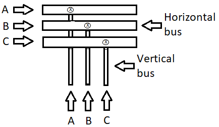
Figure 7. Phase arrangement for a 3-phase system. Image used courtesy of Lorenzo Mari
- Designate the phase with higher voltage to ground on 3-phase, 4-wire, delta-connected systems as B.
- Mark other busbar arrangements built for additions to existing installations.
Exception: If identified, back-to-back units with shared vertical buswork may have a C, B, and A phase arrangement.
Section 430.97(C) Minimum Wire-Bending Space
- Follow Section 312.6 to determine the minimum wire bending space at the MCC terminals and minimum gutter space.
The wire-bending space in an MCC is the designated room required for properly bending and routing wires and cables within its compartments.
Sufficient space for bending wires prevents sharp bends that can damage insulation and create faults or safety hazards.
The wire-bending space contemplates the installation work and the finished job. Exceeding the conductor bend radius once during the installation may damage the insulation.
Section 430.97(D) Spacings
- Follow Table 430.97(D) to determine the spacings between the MCC bus terminals and other bare metal parts.
For voltages not over 600 V, Table 430.97(D) requires, for example, 25.4 mm of clearance between a live bus and ground, 25.4 mm of clearance between phases of opposite polarity through the air, and 50.8 mm of clearance between phases of opposite polarity across a surface.
Section 430.97(E) Barriers
- Use barriers to isolate service busbars and terminals from the rest of the equipment in all service-entrance MCCs.
These barriers protect maintenance personnel, ensuring they can work safely without the risk of accidentally touching live electrical components.
NEC Section 430.98 Marking
Section 430.98(A) Motor Control Centers
- Mark MCCs per Section 110.21, “Marking.” The marking must be visible after installation.
- Include the common power bus current rating and the MCC short-circuit rating.
Marking refers to the labeling and identification of an MCC along with its components, circuits, and internal connections. This marking includes the manufacturer’s name, trademark, or other descriptive labels to identify the product and information about voltage, current rating, short-circuit rating, bus bracing, and wattage. Also, markings may include hazard warnings and details related to circuit breakers, fuses, motor starters, and other devices, along with schematics illustrating the internal layout and connections. It is essential that the marking is durable and can withstand specific environmental conditions.
The marking of the available fault current allows the electricians and inspectors to ensure compliance with sections 110.9 and 110.10. These sections refer to the overcurrent device interrupting rating, total circuit impedance, equipment short-circuit current ratings, and other circuit characteristics. All these circuit parameters must be selected and coordinated to ensure that the overcurrent device will clear the fault without significant damage to the electrical equipment.
Section 430.98(B) Motor Control Units
- Comply with Section 430.8, “Marking on motor controllers.”
Section 430.8 outlines the marking requirements for motor controllers. The markings on a motor controller must include the manufacturer’s name or identification, the voltage rating, the current or horsepower rating, the short-circuit current rating, and additional information indicating the appropriate applications for which the controller is suitable.
These markings guarantee the proper and safe operation of the motor controllers, fulfilling the electrical system’s requirements.
NEC Section 430.99 Available Fault Current
- Document the available short circuit current at the MCC and ensure it is accessible to those authorized to inspect, install, or maintain the system, along with the calculation date of the short circuit current.
This requirement includes marking the MCC nameplate with the available fault current and the date of the short-circuit current calculation.
Determining the available fault current at the MCC is essential for ensuring its rating is correct for the worst-case fault condition it may face.
Electricians and inspectors can review the short-circuit calculations to ensure that the available fault current in the MCC supply circuit does not exceed the MCC’s short-circuit rating.
To warrant the MCC rating can handle the available short-circuit current, observe the maximum amount of fault current delivered to the MCC during a fault condition and compare this value with the MCC short-circuit rating shown on the nameplate. If the MCC has a short-circuit rating equal to or greater than the available fault current, then the installation complies with Section 110.10.
Motor Control Center Takeaways
- A Motor Control Center (MCC) is a collection of panels designed to supply power, control, and protect motor circuits.
- The MCC requirements include overcurrent protection, use as service equipment, grounding, and construction.
- Construction requirements include arranging phases and the horizontal runs through various sections.
- MCCs may function as service equipment.
- An equipment grounding conductor must connect the sections of an MCC to avoid dangerous voltages.
- It is essential to hold busbars firmly in place.
- Keep appropriate wire-bending space at the MCC terminals and adequate gutter space.
- The MCC must have a short-circuit rating equal to or greater than the available fault current.
- The documentation for fault current must be available and include the calculation date.
Related Content