Facebook
 Google
 GitHub
 Linkedin
Motor Starters Part 9: Troubleshooting VFDs
The article introduces how to troubleshoot a VFD to eradicate the faults that might be hindering it from performing up to expected industrial and application standards.
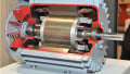
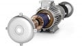
Understanding how variable frequency drives (VFDs) work and how they interact with the application process is important in improving the product quality and production process.
VFDs face unique challenges and often require repair or replacement. Most VFDs have an LED or LCD screen used for communication to indicate errors, with some using an open interlock. The problem with a poorly functioning VFD or a completely non-functional VFD can be external or internal. This article will demonstrate how to troubleshoot a VFD both externally and internally to eliminate faults and failures.
How to Troubleshoot a VFD Externally
While troubleshooting a VFD, start with basic preventive measures from a maintenance checklist. Below are the necessary steps to follow for a well-organized preventative maintenance schedule:
- Visually inspect the whole variable frequency drive system: Check for any form of dripping, extreme temperatures, running water, debris, high humidity, or corrosive agents near the VFD.
- Check the power wiring connections to ensure they are tight and well-connected: Poor wire connections are dangerous as they play a big role in destroying the IGBTs, overcurrent trips, failure of the input rectifiers, and burning of contactors and switch connectors.

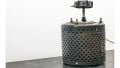
Figure 1. VFD power cable connections. Image used courtesy of Simon Mugo
- Check the incoming amount of line currents and voltages: A good incoming 3-phase alternating current shouldn’t have a deviation exceeding 5%. Unbalanced line voltage is a recipe for challenges affecting the VFD, such as overvoltage and undervoltage tripping originating from line surges and sags. Ensure that the incoming current is also at the recommended amount to protect the VFD against high starting current and overcurrent faults.
- Check the drive’s output current and voltage: For most variable frequency drives, the output voltage which originates from the inverter must be balanced to a specified volume before running the electric motor. Large deviations in the current and voltage can subject the motor to problems, such as frequent shaking or vibrating. Motor problems are also contributors to VFD failure.
How to Troubleshoot a VFD Internally
This is a more vigorous and complex process requiring expertise to carry it out. Following are step-by-step instructions on troubleshooting the VFD to eradicate internal failures.
Static Testing
Testing the Rectifying Circuit
Inside the variable frequency drive, locate the N and P terminals connected to the DC power supply. Adjust the multimeter to the scale of X10 resistance. Connect the multimeter’s red cable to terminal P and the black cable to terminals R, S, and T.
The resistance in these terminals should be equal and in dozens. Interchange the multimeter terminal cable connections where black now goes to terminal P and red goes to R, S, and T in that order. Now the resistance is supposed to be nearly infinite. Connect the red multimeter cable to the DC power supply N terminal and repeat the above. The results should be the same.
If the results are as below, then the VFD circuit functioning is abnormal:
- The imbalanced resistance of the three phases implies that the bridge rectifier has failed.
- If, during the connection of the red cable of the multimeter to terminal P, the multimeter shows the infinite value of resistance, then the bridge rectifier or the system starting resistance has failed.
Testing the VFDs Inverter Circuit
Connect the red cable of the multimeter to terminal P and then the black cable to terminals U, V, and W, where the results should be a dozen of output resistance, and all U, V, and W should have the same resistance value.
If interchanged, then the value of the resistance should return an infinite value. Now connect the red cable to terminal N and redo the steps above. The results should be the same. If they are not, there https://eepower.com/power-electronics-textbook/vol-i-electrical-power-systems-design/chapter-1-introduction-power/basic-dc-circuit-theory/will be a fault in the inverter circuit module.
Dynamic Testing
Dynamic testing can be done once the static tests return a normal result. Before doing the dynamic testing, perform the following:
- Confirm the input voltage to the VFD is correct before powering it on. Connecting a VFD to voltages above its rated value (for example, connecting a 220 V VFD to a 415 V power supply) will blow out its important electronic components.
- Check for proper connection of the transducer broadcast port. Confirm if the connection is firm or loose. If abnormally connected, expect the VFD to fail through unexpected burn-off or other unpredictable impacts.
- Power on the VFD to check the fault displayed and why it occurred.
- If the VFD does not display the fault, cross-check for the correctness of the normal parameter settings. Restore the parameters to normal. Run the VFD at no load condition to carry out the test of the output voltages U, V, and W power phases. If the phase results are unbalanced or experience loss, then there is a failure in the driver board and the module.
- If the condition is a normally expected output voltage, connect the load and test the driver while under full load connection.
VFD Failure Diagnosis
Damaged Rectifier Module
This originates from internal VFD short circuits and power grid voltages. After checking that the VFD has no short circuits, replace the rectifier bridge. Always make sure to check for the stability of the power grid supply, especially when the drives work in the same environment as devices that corrupt the grid, such as welding machines.
Damaged Inverter Module
This is caused by either driver or motor failure. After repairing the system drive circuit and ascertaining that the drive waveform is up to the defined standard, carry out module replacement. After replacing the drive module and the board, check the load and motor connection cables to ensure there is no failure before starting the VFD.
Driver Powered on But Zero Display
This is caused by a faulty power supply switch, a damaged resistor circuit, a destroyed soft VFD charging circuit, or a damaged panel.
Driver on but has an Undervoltage or Overvoltage Display
This originates from the loss of the input voltage phase due to damp and aging circuitry. To test the troubleshooting, inspect the board’s circuit components to remove the destroyed one.
Displays Earth Short Circuit or Current When Powered on
This appears when the current-detecting circuitry, e.g., amplifiers, hall elements, etc., are destroyed. Replace any destroyed elements.
Displaying Overvoltage on Starting
This is caused by a faulty drive circuit or counter module.
Key Takeaways of Troubleshooting VFDs
- Before troubleshooting, it is important to have the VFD manual and maintenance checklist.
- VFD troubleshooting involves two stages: external and internal.
- External troubleshooting involves visual inspection, and checking the power wiring connection, the number of incoming line currents and voltages, and the output voltages and currents from the drive.
- Internal problems can be identified and eliminated by performing static and dynamic testing.
- Static testing involves rectifying and inverter circuits.
- Dynamic testing can only be performed after static testing.