Facebook
 Google
 GitHub
 Linkedin
Determining Power Factor Using the Two-Wattmeter Method
The ratio of true power to apparent power is called the power factor of the load. When the two-wattmeter method is used to measure the power dissipated in a balanced load, the power factor of the circuit can also be determined from the meter readings.
What is Power Factor?
Power factor is the ratio between the true power in watts and the apparent total power in volt-amps of an electrical load or system. Power factor is a measure of how efficiently the line current of a load or system is being converted into useful work output. The ideal power factor is unity (1 or 100%). Anything less than 1 means additional power is required to accomplish the actual task.
The power triangle below in Figure 1 illustrates the phase angle (θ) between true and apparent power. The cosine of the phase angle is known as the power factor (PF), and its value is inversely proportional to the amount of reactive power. The smaller the angle θ, the less reactive power present and the greater your power factor is.
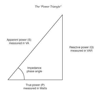
Figure 1. Power factor triangle. Image used courtesy of Allaboutcircuits
Apparent power (VA) is equal to or greater than the true power (watts), depending on the power factor (PF). Therefore, when sizing circuits or equipment, you must size the circuit equipment according to the apparent power (volt-amperes) and not the true power (watts). Formulas that can be used for determining apparent power are as follows:
\[Apparent\,Power(VA)=Volts\times Ampere(Single\,Phase)\]
\[Apparent\,Power(VA)=1.732\times Volts\times Ampere(Three\,Phase)\]
\[Apparent\,Power=\frac{True\,Power}{Power\,Factor}\]
\[Apparent\,Power=\sqrt{(True\,Power)^{2}+(Reactive\,Power)^{2}}\]
True power (watts) is the energy consumed by the resistive part of an AC circuit. The true power of a circuit that contains inductive and/or capacitive reactance in addition to resistance is measured with a wattmeter and can be calculated by use of one of the following formulas:
\[True\,Power(W)=Volts\times Ampere\times Power\,Factor(Single Phase)\]
\[True\,Power(W)=1.732\times Volts\times Ampere\times Power Factor(Three Phase)\]
\[True\,Power=\sqrt{(Apparent\,Power)^{2}-(Reactive\,Power)^{2}}\]
Reactive power (VARs) is power supplied to a reactive load. Almost all AC circuits include reactive power in the form of inductive reactance and/or capacitive reactance. Inductive reactance is by far the most common since all motors, transformers, solenoids, and coils have inductive reactance. The formulas for determining reactive power are:
\[Reactive\,Power(VARs)=Volts\times Ampere\times Sinθ(Single\,Phase)\]
\[Reactive\,Power(VARs)=1.732\times Volts\times Ampere\times Sinθ(Three\,Phase)\]
\[Reactive\,Power=\sqrt{(Apparent\,Power)^{2}-(True\,Power)^{2}}\]
Power factor (PF) is the ratio of true power (watts) to apparent power (VA) and is expressed as a percentage that does not go above 100 %. Power factor measures how far the current and voltage are out of phase with respect to each other. Unity power factor (1 or 100%) can only occur if the AC circuit supplies resistive loads or when capacitive reactance (XC) is equal to inductive reactance (XL). When the power factor is less than 100 percent, the circuit is less efficient and has a higher operating cost because not all current performs useful work.
The formulas for determining the power factor are
\[Power\,Factor=\frac{True\,Power}{Apparent\,Power}\]
\[Power Factor=\frac{Watts}{VA}\]
Power Factor Determination
Consider the phasor diagram for a balanced Y-connected load, as shown in Figure 2. The phase voltages EAN, EBN, and ECN, have 120° phase differences and line voltages EAB, EBC, and ECA are 30° ahead of EAN, EBN, and ECN, respectively. The line currents IA, IB, and IC (also the phase currents in a Y-connected load) each lag the related phase voltage by phase angle φ.
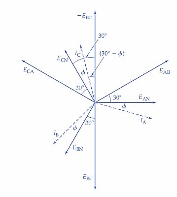
Figure 2. Phasor diagram for a two-wattmeter power measurement method with a balanced Y-connected load. The load power factor can also be determined from the meter readings. Image used courtesy of Amna Ahmad
Now, look at the circuit diagram in Figure 3. The current coil of wattmeter W1 carries line current IA, and the potential difference across its voltage coil is line voltage EAB. The phase difference between EAB and IA is (30°+φ) (see Figure1). Consequently, the power indicated by W1 is
\[P_{1}=E_{AB}I_{A}cos(30°+ф)\]
Because EAB is line voltage VL, and IA is line current IL,
\(P_{1}=V_{1}I_{L}cos(30°+ф)\) (1)
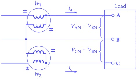
Figure 3. The two-wattmeter method is most often used for measuring three-phase power. It is appropriate for Δ- or Y-connected, balanced or unbalanced loads. The load power is determined by adding the meter readings. Image used courtesy of Amna Ahmad
In Figure 3, the current flowing in the current coil of wattmeter W2 is line current IC. The potential difference across its voltage coil is -EBC. If the voltage coil of W2 had been connected with its ± terminal to line B, the voltage would be +EBC. But when connected as illustrated, the voltage coil potential difference is -EBC. As shown in the phasor diagram in Figure 2, there is a 30° difference between -EBC and ECN. Because IC lags ECN by angle ф, the phase difference between –EBC and IC is (30°- φ). The power indicated by W2 can now be written as
\[P_{2}=E_{BC}I_{C}cos(30°+ф)\]
Or
\(P_{2}=V_{L}I_{L}cos(30°-ф)\) (2)
\[P_{2}+P_{1}=V_{L}I_{L}[cos(30°-ф)+cos(30°+ф)]\]
\[=V_{L}I_{L}(2\,cos\,\,cos\,30°cos\,ф)\]
\[=\sqrt{3}V_{L}I_{L}cosф\]
And
\[P_{2}-P_{1}=V_{L}I_{L}[cos(30°-ф)-cos(30°+ф)]\]
\[=V_{L}I_{L}sinф\]
\[\frac{P_{2}-P_{1}}{P_{2}+P_{1}}=\frac{V_{L}I_{L}sinф}{\sqrt{3}V_{L}I_{L}cosф}=\frac{1}{\sqrt{3}}tanф\]
Giving,
\(ф=tan^{-1}\sqrt{3}\left[\frac{P_{2}-P_{1}}{P_{2}+P_{1}}\right]\) (3)
In deriving Equation 3, it was assumed that ф is less than 60°. When ф is greater than 60°, (30°+ф) exceeds 90°, and cos (30°+ф) becomes a negative quantity, making the reading on wattmeter W1 negative. As noted, to get a positive indication, the connections to either the current coil or the voltage coil must be reversed, and the power measured by the wattmeter must be recorded as a negative quantity.
The two-wattmeter method does not indicate whether the calculated power factor is leading or lagging. This must be determined by considering the load. A largely inductive load has a lagging power factor, and a predominantly capacitive load has a leading power factor.
Example
The readings of the two wattmeters connected to measure the total power in a three-phase wye-connected 400-Volts system are 4 kW and 6 kW. Calculate the power factor.
Solution
Wattmeter 1 reading = P1 = 4000 W
Wattmeter 2 reading = P2 = 6000 W
Voltage = VL = 400 V
Using equation 3,
\[ф=tan^{-1}\sqrt{3}\left[\frac{P_{2}-P_{1}}{P_{2}+P_{1}}\right]\]
\[ф=tan^{-1}\sqrt{3}\left[\frac{6000-4000}{6000+4000}\right]\]
\[ф=tan^{-1}\sqrt{3}\left[\frac{1}{2}\right]=tan^{-1}(0.3464)=19.106°\]
Power factor
\[cosф=cos(19.106°)=0.945\]
Key Takeaways of the Two-wattmeter Method
The two-wattmeter method is most often used for measuring three-phase power. It is appropriate for Δ- or Y-connected, balanced or unbalanced loads. When this method is employed to measure the three-phase power dissipated in a balanced load, the power factor of the circuit can also be computed from the meter readings. In the two-wattmeter method, there is no indication of whether the power factor calculated is leading or lagging. This must be determined by considering the load.