Facebook
 Google
 GitHub
 Linkedin
A Deeper Understanding of Power Factor
This article coves power factor as a general concept, offering explanations, equations, and examples utilizing power factor, true power, and apparent power.
What is power factor and what is its importance? The definition is commonly presented for linear AC circuits (formed by resistors, inductors, and capacitors), but really this is only one case. This article introduces power factor as a general concept, explains its importance, and shows how to calculate, simulate, or measure it in real applications.
How to Calculate Power Factor
Power factor is an important parameter that comes into play every time a load is connected to the electric distribution network. The system can be modeled as a simple circuit:
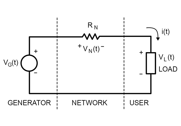
where:
vG(t) = instantaneous voltage of line generator
vN(t) = instantaneous voltage across network equivalent resistor
vL(t) = instantaneous voltage of generic load connected to the network
i(t) = instantaneous current flowing through the circuit
It is important to note that load is indicated as a generic load, so the waveform voltages and current can be:
-
sinusoidal, in case of a linear load (resistors, capacitors, inductors)
-
not sinusoidal, in case of a nonlinear circuit (i.e., switching mode power supply (SMPS) containing diodes, transistors, etc.)
Calculating a Load’s True Power
In both cases the true power provided to the load can be calculated as:
$$P_{L} = \frac{1}{T} \int^T_0 P_L(t)dt = \frac{1}{T} \int^T_0 V_L(t)i(t)dt \ \ \ \ [W]$$
The true power can be calculated, or measured, as the average of the product of instantaneous values of V and I.
If we suppose (real case) that:
$$vN \ll vL$$
then we have:
$$v_L \approx v_G$$
so the generator provides a true power that is almost the same transferred to the load:
$$P_G \approx P_L$$
What about power losses associated with the distribution network? Let’s calculate:
$$P_N = R_N I_{RMS}^2$$
PN depends only on the RMS value of the current, which in turn depends on the connected load.
Understanding Power Factor Through Circuit Simulation
In order to show these concepts, we can consider the following simple circuits simulated with LTSpice:
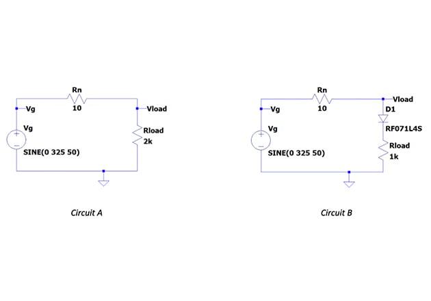
Fig.1
The simulation has been performed by using the typical voltage source 230Vac (sinusoidal 230VRMS, VPK=325V), measuring voltage (Vload), and current (Iload) at the load, and calculating the power for circuit A (pure resistive load) and circuit B (half-wave rectified resistive load).
Figures 2 and 3 the waveforms of Circuit A demonstrating voltage and current at the load and voltage-current product at the load.

Figure 2. Circuit A: waveforms of voltage and current at the load

Figure 3. Circuit A: waveform of voltage-current product at the load
From the waveforms above we have:
-
The RMS value of the voltage at the load is almost 230V as expected (RMS value, Figure 2)
-
The voltage and current at the load are both sinusoidal and in-phase (pure resistive load, Figure 2)
-
The true power at the load is PA=26W (average value, Figure 3), measured as the average value of the voltage-current product.
-
The power loss through the network can be calculated as PNA=RNIRMS2=10∙0.1142=130mW
Now let’s check those same waveforms of Circuit B, shown in Figures 4 and 5.

Figure 4. Circuit B: waveforms of voltage and current at the load

Figure 5. Circuit B: waveform of voltage-current product at the load
From the waveforms above we have:
-
The RMS value of the voltage at the load is almost 230V as expected (RMS value, Figure 4)
-
The voltage at the load is sinusoidal (Figure 4)
-
The current at the load is half-wave rectified (Figure 4)
-
The true power at the load is PB=26W (Figure 5, average value), measured as the average value of the voltage-current product.
-
The power loss through the network can be calculated as: PNB=RNIRMS2=10∙0.1602=256mW
The following table summarizes the collected data for both circuits:
| Circuit A | Circuit B | |
| VLOAD | 230V (RMS) | 230V (RMS) |
| ILOAD | 114mA (RMS) | 160mA (RMS) |
| PLOAD | 26W | 26W |
| PN | 130mW | 256mW |
Even if the true power at the load is the same, the network losses associated with Circuit B are almost twice the network losses associated with Circuit A.
We could say “Circuit A makes better use of the line,” in the sense that for the same true power transferred to the load (the power for which the user pays), the owner of the network has lower losses on its infrastructure.
In order to quantify whether the circuit is making good use of the line, the concept of apparent power must be introduced.
What is Apparent Power?
Apparent power can be defined as the power equivalent to a pure resistive load with same RMS values of V and I of the real load. The apparent power can be calculated, or measured, as the product of RMS values of V and I. Mathematically, it is represented as:
$$S = V_{RMS} I_{RMS} \ \ \ \ [VA] $$
If we calculate the apparent power for Circuit A and Circuit B, we obtain:
$$S_A = 230V \cdot 114mA = 26VA \ \ \ \ (Circuit A)$$
$$S_B = 230V \cdot 160mA = 36.8VA \ \ \ \ (Circuit B)$$
Circuit B is taking 26W (PB) from the network, but SB states that it generates network losses like an equivalent pure resistive load taking 38.6W from the line. With this, we can conclude that Circuit B is using the line in a less-than-ideal way.
Circuit A really is a pure resistive load, so we have SA=PA. This shows us why Circuit A is using the line in a perfect way.
Tying All This Back into Power Factor
In the end, the parameter to quantify the quality of usage of the network, from the network losses point of view, is the so-called power factor:
$$PF = \frac{P}{S} = \frac{true power}{apparent power}$$
For the considered circuits, power factor can be calculated as:
| $$PF_A = \frac{P_A}{S_A} = \frac{26W}{26VA} = 1$$ |
Circuit A
|
| $$PF_B = \frac{P_B}{S_B} = \frac{26W}{36.8VA} = 0.7$$ |
Circuit B
|
From the definition, power factor has a value in the range 0-1. Typically, for real applications, a PF>0.9 is requested in order to maintain low network losses.
Review of Power Factor Concepts
This article presented the concepts of apparent power and power factor and showed how they are applicable to a generic circuit — not only to sinusoidal systems with linear loads (resistive, inductive, capacitive) but also non-sinusoidal even if these concepts are usually presented in this particular case.
Through the general definitions presented in the article, it has been illustrated how to measure (or simulate) the true power, apparent power, and power factor in real applications (using a typical case of LED drivers for an AC line).
Related Content