 Facebook
 Google
 GitHub
 Linkedin
Triangle Of Power And Power Factor
Power in AC Systems
In a purely resistive AC circuit, power is simply power. If we add inductance or capacitance to the circuit, the situation becomes very different. As you now know, capacitance and inductance affect the phase relationship between voltage and current, and we need to understand some specialized techniques before we can analyze power when voltage and current are not in phase.
Active and Reactive Power
Power is voltage multiplied by current. This definition doesn’t require any additional explanation when we’re working with a resistive AC circuit: the current and voltage have perfect phase alignment, and consequently we will always be multiplying two positive numbers or two negative numbers.

Figure 1. In this case, power calculations will always result in a positive number, because phase alignment ensures that we will multiply a positive voltage by a positive current or a negative voltage by a negative current.
However, even a small phase difference between current and voltage will create two portions of the AC cycle in which one of the quantities is positive and the other is negative. The calculated power during this section of the waveform will be a negative number.

Figure 2. Phase misalignment between current and voltage leads to a negative power value from 0° to approximately 30° and from 180° to approximately 210°.
Now we do need some additional explanation. What is a negative power? Can a component release negative quantities of energy into the surrounding environment? Negative power can be a bit confusing at first. A negative power value indicates that power is not doing work. To be more specific, the negative-power portions of the AC cycle indicate that power is delivered to the system but does not transfer energy to the system; rather, the energy is returned to the source.
This type of electrical power is called reactive power. This name will be easy to remember if you already know that inductors and capacitors—which create phase shift, which in turn leads to reactive power—are considered reactive components. Reactive power does not transfer energy from source to load, but it is not “wasted,” because reactive loads cannot function without it.
Power that does work somewhere in the load circuit is called active power (“real power” and “true power” are also used). Active power is active at the load, i.e., it is really doing something, such as heating up a soldering iron or illuminating a laboratory. Reactive power is distinguished from active power by the use of a different unit. Volt-ampere reactive (var) is the unit for reactive power, and active power uses the unit that we already know, namely, watts.
Understanding the Power Triangle
Active power is denoted by P, and reactive power is denoted by Q. Let’s introduce three additional quantities that are involved in the analysis of power consumption in reactive circuits:
- Complex power, denoted by S, is the vector sum of real power and reactive power.
- Apparent power, denoted by |S|, is the magnitude of complex power. It uses the unit volt-amperes (VA) rather than watts.
- Power factor, abbreviated PF, will be discussed shortly.
The following diagram is referred to as the power triangle.

Figure 3. The power triangle provides a visual (and mathematical) representation of a system’s active power, reactive power, and apparent power.
Apparent Power
If you measure a load’s RMS voltage and RMS current and then multiply these two values, the result is apparent power. That’s why it’s called “apparent”: it corresponds to the power dissipation that we would expect based only on RMS voltage and current. However, we now know that the apparent power might be higher than the real power dissipation because a phase difference between voltage and current creates reactive power that contributes to apparent power.
Consider what happens, though, in a purely resistive circuit. No reactive power is present; consequently, the angle between active power and complex power will be zero. So in this case, apparent power (i.e., the length of the complex power vector) will be equal to active power.
Apparent power can also be described as the amount of power delivered to a system by the source. Again, this is not the same as the actual power dissipation, because some of that delivered power is returned to the source rather than dissipated at the load.
Power Factor
The ratio of active power to apparent power is called the power factor. In other words, power factor is the power usefully employed by a device, P, divided by what is carried to that device via the power grid, |S|. Power factor can also be calculated as the cosine of the angle of the load impedance (i.e., the angle between active power and complex power, labeled θ in Figure 3).
In a purely resistive circuit, there is no reactive power, and consequently active power is equal to apparent power and the power factor is one. The power triangle has been reduced to a line. In general, we want the power factor to be as close to one as possible because this indicates that the grid’s electrical energy is being used more efficiently.
Let’s say that the grid needs to supply power for a 240 W motor. If this motor (along with its control circuitry) is designed to have a power factor of one, it will draw 2 A of current from the grid. If the power factor is lower than one, it will draw more than 2 A of current, but the real power dissipation is still 240 W. Thus, the power grid needs to deliver additional current in order to accomplish the same amount of work, and this leads to more resistive power loss in the distribution wires and higher equipment costs.
Both capacitors and inductors create the phase differences that lead to reactive power, but their specific effects on phase are exactly opposite and can balance each other out. Power factor correction refers to the process of improving power factor by deliberately adding reactance (such as a capacitor) into a circuit in such a way as to mitigate the effects of other reactance (such as the inductance of a motor coil). You’ll often see banks of very large capacitors on site at industrial locations. Their purpose is to counteract the effect of inductors and thus to improve power factor.
The Impedance Triangle
While we’re on the topic of power factor, let’s briefly discuss another type of triangle that is useful in AC power analysis. The impedance triangle conveys the impedance characteristics of a circuit; the horizontal and vertical sides correspond to the resistance and reactance, respectively, and the hypotenuse is the complex impedance.

Figure 4. The impedance triangle. You can also think of this as a graphical representation that uses the complex plane. The overall impedance is the vector, which consists of a real part (along the horizontal axis) and an imaginary part (along the vertical axis).
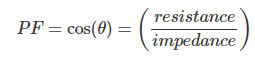
The angle between resistance and impedance is the same as the angle between active power and complex power in the power triangle. This gives us another way to calculate power factor:
Next: Passive Components in AC Circuits
We’ve covered some important topics related to AC power dissipation, and we introduced the power triangle, which is a useful tool that can help you analyze AC circuits that include reactive components. In the next page we’ll continue our study of passive components in the context of AC circuit analysis.