Facebook
 Google
 GitHub
 Linkedin
Characteristics and Uses of Zig-Zag and Wye-Delta Grounding Transformers
This article analyzes the roles of zig-zag and wye-delta transformers in grounded power systems.
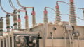
A cost-effective way to obtain a neutral to ground existing ungrounded systems is to use grounding transformers. Commonly used types of grounding transformers are the interconnected-star (zig-zag) and the wye-delta. Grounding transformers are important electromagnetic devices machines in power systems.
The Role of Grounding Transformers in Grounded Power Systems
The grounding of a power system is vital since the availability, short circuit withstands capability, transient overvoltages, basic insulation level (BIL), and other factors depend on the method of neutral grounding.
Grounding transformers create a grounded neutral connection on an ungrounded three-phase system — like a three-wire system supplied from a delta secondary — providing a path for ground-fault zero-sequence currents. They also allow the flow of the triple-harmonics of the exciting current in an ungrounded transformer.
Two goals targets in grounding transformer design are low zero-sequence impedance and small no-load losses (hysteresis and eddy current losses). These elements play a vital role in the effectiveness and cost of grounding.
There are two more common configurations of three-phase grounding transformers or three-phase grounding banks:
- Wye-delta that may also be employed to supply auxiliary power
- Interconnected-star or zig-zag, with or without secondary winding
The standard practice in the USA is solid grounding for voltages up to 1000 V and above 15 kV, and through an impedance from 1000 V to 15 kV.
Grounding transformers connect to three-phase lines. Under normal conditions, the rated voltage is balanced and phase-shifted by 120° and only the exciting current circulates through the windings.
The currents are in phase flow through the neutral connections. These co-phasal currents are:
- Triple-harmonics of the exciting current
- Zero-sequence currents coming from:
- b1. Unbalanced loads
- b2. Faults involving ground
Grounding transformers may also be utilized in a power system to reduce the impedance to ground-faults and secure enough ground current for relaying. They can also limit the level of the ground-fault current with the transformer impedance only or, if required, with a resistor or an impedance inserted in the transformer neutral or inside the delta winding of a wye-delta connection.
Usually, grounding transformers are short-time devices. For this reason, their size and cost are less than that of a continuous duty transformer of the same capacity.
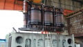
Zig-Zag Grounding Transformer
A type of grounding transformer frequently used is the interconnected-star or zig-zag. Typical zig-zag transformers do not have a secondary winding and exhibit useful winding connections that only allow the flow of currents that are in phase through the neutral. They may be three-phase transformers or a bank of three single-phase units.
The zig-zag arrangement is the most common because of its lower cost and the ability of the iron core design to limit the flow of the triple-harmonic fluxes. Zig-zag transformers are smaller in size than wye-delta transformers for the same zero-sequence impedance.
Figure 1 shows two coils with the same number of turns wound in each leg of the magnetic core — one termed outer coil (zig), and the other inner coil (zag). The terminals of the same relative polarity of the outer coil of one leg and the inner coil of the next leg are connected in such a way that the circuit is symmetrical and the current flows in opposite directions. The phases of the ungrounded system connect to the outer coils, and the inner coils form the neutral.
_Fig1a.JPG)
Figure 1. Zig-zag three-phase grounding transformer, core-type construction
The currents entering through terminals a, b and c, flow in one coil in the opposite direction to the other coil. If these currents are equal in magnitude and phase, they leave terminal n and do not produce a net magnetomotive force (MMF) in any of the legs. Then, there is no opposition to their flow other than the small leakage impedance. This concept applies equally to the triple-harmonics of the excitation current of a transformer and the zero-sequence currents of faults involving the earth.
With an impedance inserted in the neutral circuit to ground, this impedance and the leakage impedance limit the fault current.
In each leg, the positive- and negative-sequence currents generate a net MMFmmf coming from the difference of two identical components phase-shifted by 60°. Without an additional winding to carry a supplementary current, the current magnitude in the windings is just what is needed to excite the core to the flux density required to support the applied terminal voltage.
Figure 2 shows a voltage phasor diagram for a zig-zag connection and Figure 3 shows the flow of zero-sequence currents for a line-to-ground fault.
_Fig2.JPG)
Figure 2. Phasor voltage diagram in zig-zag grounding transformer
_Fig3.JPG)
Figure 3. Zero-sequence current flow in zig-zag grounding transformer
In conclusion, the zig-zag connection poses a high magnetizing impedance to the flow of balanced positive- and negative sequence currents and a much lower leakage impedance to the flow of triple-harmonics and zero-sequence currents. In a power system, a zig-zag transformer with the neutral connected to ground provides a path for zero-sequence currents coming from ground faults. It has little impact on positive- and negative-sequence currents.
Wye-Delta Grounding Transformer
The connection of a wye-delta grounding transformer is the same as a conventional power transformer but does not necessarily supply a load on the delta-connected secondary.
As before, only the excitation current flows with balanced three-phase voltages applied. Under this condition, the voltages induced in the secondary are also balanced, and the net voltage around the delta windings is zero.
Under a single line-to-ground fault, the voltage of one of the primary windings collapses, and the voltage induced in its secondary winding is zero. The net secondary voltage is no longer zero, and a large zero-sequence current flows in the closed delta. This zero-sequence current reflects the primary and flows to the fault location, as seen in Figure 4.
_Fig4.JPG)
Figure 4. Zero-sequence current flow in wye-delta grounding transformer
In high-resistance grounding, connecting the grounding resistor across the broken delta will limit the fault current to the desired value.
Voltage Equalization with Wye-Delta Grounding Transformers
Line-to-neutral voltage distortion appears as a consequence of triple-harmonic voltages in ungrounded wye-wye transformer banks or three-phase shell-type units. With this winding connection, the voltages to neutral appear unbalanced and nonsinusoidal. Equalizing these voltages requires the removal of the triple-harmonics with a wye-delta grounding transformer.
The wye-delta grounding transformer allows the flow of the exciting current triple-harmonics, thereby achieving a sinusoidal flux wave and inhibiting the triple-harmonics of the line-to-neutral voltage.
Figure 5 shows a wye-delta grounding transformer with the primary grounded, connected to the secondary winding of the ungrounded wye-wye bank.
Figure 5. Flow of triple-harmonics exciting currents of the wye-wye power transformer
Grounding both neutrals or connecting them with wire allows the triple-harmonics components of the wye-wye bank to flow in its secondary windings and the primary windings of the grounding transformer. The triple-harmonics in the primary windings induce triple-harmonics circulating currents in the delta secondary. Then, the delta secondary will carry the triple-harmonics of the wye-wye bank exciting current plus the triple-harmonics of the grounding transformer exciting current.
A Review of Grounding Transformers
The purpose of a grounding transformer bank or three-phase grounding transformer is to ground the neutral of an otherwise isolated-neutral system.
The most common configurations are wye-delta and interconnected-star or zig-zag.
If the system voltage is symmetrical, the line-to-neutral voltages are balanced, and the grounding transformer takes just sufficient current to excite it.
If there is a fault or an unbalanced load in the system, the line-to-neutral voltages are no longer balanced, and co-phasal currents, of the same magnitude, may flow in the transformer phases. These currents are the zero-sequence components. In the zig-zag connection, the zero-sequence currents produce no net magnetization of the iron core, because they flow in opposite directions in each leg and only see the low leakage impedance of the coils.
The grounding transformers offer a much smaller impedance to zero-sequence currents than to the exciting currents in a balanced system, providing a low impedance route to ground and keeping the neutral at ground potential.
Under a line-to-ground fault, the grounding transformers will allow let a suitably large fault current to activate the protection schemes. Grounding transformers also allow the flow of triple-harmonics to equalize the voltages in some transformer connections.