Facebook
 Google
 GitHub
 Linkedin
Determining Rated Current
By determining the rated current for power inductors, components can be selected with greater optimality.
This article is published by EEPower as part of an exclusive digital content partnership with Bodo’s Power Systems.
The definition of rated current continues to vary among passive component manufacturers in the power electronics industry despite the adoption of IEC standard 62024-2, which specifically describes how rated current should be measured. Because of this, misconceptions can still arise about what this parameter represents and how design engineers can use it. Is it an absolute parameter? Are rated current values from different manufacturers directly comparable?
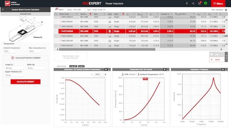
Image used courtesy of Bodo’s Power Systems [PDF]
The answer to these questions is no. As a result, parts from some manufacturers may appear better at first glance than others. However, design and component engineers should always fully understand how the manufacturer measures their components to report rated current parameters and not accept the parameters at face value.
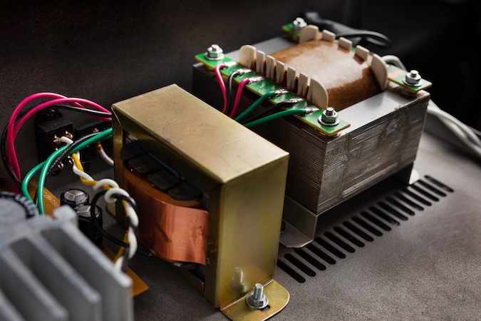
Image used courtesy of Adobe Stock
With this in mind, Würth Elektronik has developed a thermal model that calculates the rated current of power inductors given a specific size of PCB, offering design and component engineers the ability to explore how the rated current of parts is affected by different PCB dimensions.
Impact of PCB Dimensions on Rated Current
An explanation of the thermal behavior of power inductors can be found in the application note ANP096 – What do rated current values mean? How the PCB trace dimensions influence the inductor temperature rise is described. To summarize, wider traces and increased copper thickness (PCB cross-section) will reduce the thermal resistance, increasing the flow of conducted heat from the inductor. As the surface area of the PCB increases, the thermal convection and radiation resistance are reduced, increasing thermal convection and radiation transfer to the ambient environment. In this scenario of increasing dimensions, more heat can be transferred to the environment via the PCB, lowering the operating temperature of the inductor. This also means that a higher current can be applied to the part to reach the same temperature as when a PCB with smaller dimensions is used. Now, we can conceive how PCB dimensions affect the reported value of rated current in datasheets. Again, test measurement PCBs with large sizes may be used to misrepresent rated current values, and this information may not be specified in datasheets, leaving room for misinterpretation by design and component engineers.
Rated Current Calculator
To define the rated current for components when measured on different size PCBs, Würth’s Rated Current Calculator allows the user to input the desired PCB dimensions (Figure 1).
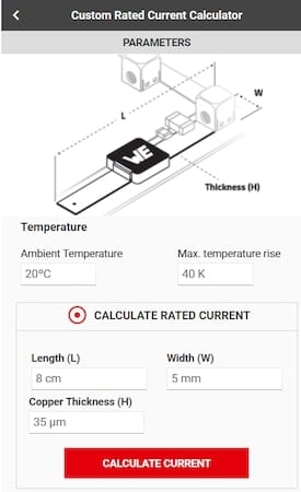
Figure 1. User interface of the Rated Current Calculator with IEC62024-2 Class A 5 mm dimensions entered. Image used courtesy of Bodo’s Power Systems [PDF]
After the PCB dimensions have been input by the user, a Custom IR column is added to the parameter table (Figure 2).
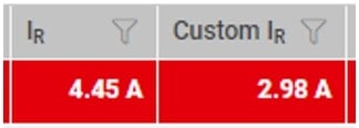
Figure 2. Datasheet Rated Current (left) and Custom Rated Current value (right) based upon dimension entered in the user interface. Image used courtesy of Bodo’s Power Systems [PDF]
In addition, the temperature rise chart has been updated to reflect the new PCB dimensions (Figure 3).
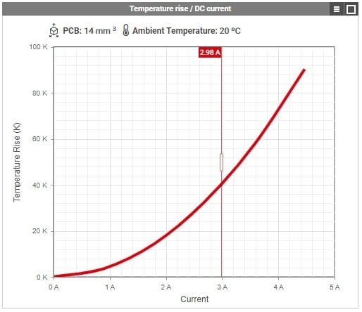
Figure 3. Temperature rise chart based upon dimension entered into the user interface. Image used courtesy of Bodo’s Power Systems [PDF]
These calculations are based on a statistical model verified by component measurements using different-sized PCBs. In this way, the user can now view the calculated rated current for Würth Elektronik power inductors on different sizes of PCB, whether that be for comparisons with other power inductors or to estimate the rated current of a part when soldered to the application PCB. It should be noted that when used to estimate the rated current in the target application, it should be remembered that other components will contribute to the heat distribution in the PCB. These components could increase the temperature of the PCB, such as the IC and capacitors, or in the case of heat sinks, lower the temperature of the PCB.
Consider the WE-LHMI (744 373 460 68), which has a rated current performance rated current of 4.45 A (Figure 4). This is measured on an IEC 62024-2 IClass C PCB. The graph displays the temperature rise as a result of the DC for this component on the IClass A 5 mm, IClass C, and IClass D PCB. In addition, the chart displays the output from the Rated Current Calculator as the data points. The calculated values are comparable to those gathered from component measurements.

Figure 4. Self-heating comparison of WE-LHMI 744 373 460 68 on different IEC 62024-2 PCBs and the calculated current for a 40 K temperature rise using the Rated Current Calculator (data points). Image used courtesy of Bodo’s Power Systems [PDF]
This comparison demonstrates how the Rated Current Calculator calculates the rated current with relative accuracy compared to rated current measurements. It also demonstrates how the rated current of a part is highly reliant on the PCB dimensions, with the inductor operating at even higher currents than the rated current on the datasheet. Additionally, it demonstrates that I RP are numbers to compare and guide in the selection of inductors before prototyping. It should be remembered that these are basic parameters, considering only DC currents with no additional heat-generating parts on the PCB. AC losses and the thermal effects of surrounding components would also have to be considered in real conditions. The actual temperature rises in the end applications will vary considerably depending on the conditions.
Rated Current Based on PCB Dimensions
Rated current values found on datasheets serve as a guide for selecting power inductors. However, the temperature rise in power inductors can be influenced by the PCB dimensions on which they are tested. These are not always comparable between all manufacturers, giving a false sense of what the rated current values represent.
Comparing similar parts from different manufacturers on the same PCBs reveals that the thermal performance is almost analogous. To this end, the Rated Current Calculator can determine the rated current of Würth Elektronik power inductors on a PCB size of the user’s choosing, allowing a rated current value to be estimated for the user’s end application or to compare inductors with competitor components.
This article originally appeared in Bodo’s Power Systems [PDF] magazine.