Facebook
 Google
 GitHub
 Linkedin
Choosing the Best Three-phase Power Measurement Method
Several methods exist to measure the power delivered to a three-phase load. Read on to learn about three-wattmeter, two-wattmeter and single-wattmeter methods.
Several methods are available for measuring the power delivered to a three-phase load. These depend on whether the load is Y- or Δ-connected, the accessibility of the load terminals, and whether the load is balanced or unbalanced.
As with all instruments, some care must be taken to connect the wattmeter correctly. The current coil terminal identified as ± should be connected to the voltage source. (Sometimes a ↓ or * is used to identify this terminal.) The ± voltage coil terminal is connected to the load terminal of the current coil. If the instrument is not connected correctly, a negative deflection may occur.
Three-Wattmeter
Figure 1 shows three wattmeters employed to measure the power in a Y-connected four-wire system with an unbalanced load. Each wattmeter measures the power dissipated in one phase of the load (VPIPCosϕ), and the total power is then the sum of the three-meter readings. All three meters in Figure 1 would read the same when the load is balanced. So, only one wattmeter is needed, and the total power is three times the meter reading.
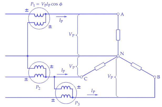
Figure 1. Three wattmeters connected to measure the power delivered to each section of a three-phase, four-wire load. The total load power is the sum of the three readings. For a balanced load, only one meter is required, and the load power is three times the meter reading. Image used courtesy of Amna Ahmad
Figure 2 shows a three-wattmeter arrangement for measuring the power in a Δ-connected load. Again, each meter indicates (VPIPCosϕ) for each of the three load sections. Only one wattmeter is required for a balanced system, and the measured quantity is then multiplied by three to determine the total power. The total power dissipated is the sum of the three meter readings.
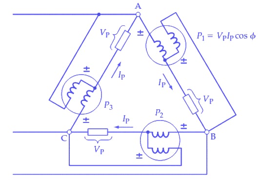
Figure 2. Three wattmeters connected to measure the power delivered to each section of a three-phase Δ-connected load. The total load power is the sum of the three readings. For a balanced load, only one meter is required. Image used courtesy of Amna Ahmad
Single-Wattmeter
In Y-connected three-wire and Δ-connected systems, no neutral conductor is available for connecting the common point of the wattmeter voltage coils. Figure 3 shows a circuit where three equal resistors are Y-connected to provide a neutral point. The single wattmeter now measures the power (P1) dissipated in one load branch, so the total power is P=3P1. This circuit is suitable only for a balanced load.
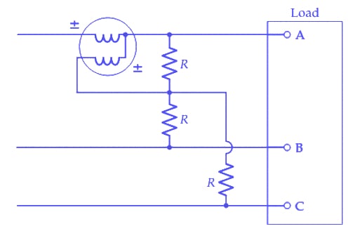
Figure 3. Single-wattmeter method of measuring the power delivered to a balanced three-wire load. The load power is three times the meter reading. Image used courtesy of Amna Ahmad
Two-Wattmeter
The two-wattmeter method is the most commonly used. The circuit for this method is shown in Figure 4.
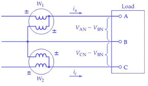
Figure 4. The two-wattmeter method of three-phase power measurement is most often used. It is suitable for Y-connected or Δ-connected, balanced or unbalanced loads. The load power is the sum of the meter readings. Image used courtesy of Amna Ahmad
The wattmeter current coils are each connected in series with one line, and the voltage coils are commoned at the remaining line, as illustrated. If the load is Y-connected, the instantaneous power dissipations in each phase can be written in terms of the instantaneous phase current and instantaneous phase voltage.
PA = (instantaneous phase current) × (instantaneous phase voltage)
PA = [line current(iA)] × [line-to-neutral voltage(vAN)]
PA = iAvAN = iAvAa
PB = iBvBN = iBvBb
PC = iCvCN = iCvCc
The total instantaneous power is
P = iAvAa + iBvBb + iCvCc (1)
The instantaneous current in meter W1 is iA and the instantaneous voltage across the voltage coil of W1 is (VAN-VBN). Similarly, the instantaneous quantities for W2 are ic and (VCN-VBN). So, the instantaneous powers measured by each of these instruments are
P1 = iA(vAa - vBb)
P2 = iC(vCc - vBb)
The sum of P1 and P2 is
P = iA(vAa-vBb) + iC(vCc - vBb) = iAvAa - iAvBb + iCvCc - iCvBb = iAvAa + iCvCc - vBb(iA + iC) (2)
With balanced or unbalanced loads, the algebraic sum of the currents at the neutral point of a Y-connected load must be zero (for a three-wire supply).
So
iA + iB + iC = 0
or
iA + iC =- iB (3)
substituting from Equation (3) into Equation (2)
P = iAvAa + iCvCc + iBvBb (4)
Equation (4) is identical to Equation (1), showing that the sum of the instantaneous powers measured by the two wattmeters is equal to the total instantaneous power dissipated in the load. A wattmeter indicates the average of the instantaneous power dissipations in a load. Consequently, the sum of the two wattmeter readings is the average power dissipated in the three-phase load.
It can also be shown that for a Δ-connected load, the two wattmeters indicate the total power dissipated. In this case, the wattmeter current coils carry instantaneous currents of (iA - ic) and (ic - iB). The voltage coil instantaneous potential differences are –vAa and -vBb. The sum of the meter readings is:
P = vAa (iA - iC) - vBb(iC - iB) = vAaiA + vBbiB - iC(vAa + vBb)
For a Δ-connected system, there is no circulating current, and
vAa + vBb + vCc = 0
or
vAa + vBb =- vCc
giving
P = vAaiA + vBbiB + vCciC (5)
Equation (5) is, once again, the same as Equation (1), showing that the sum of the meter readings gives the total load power. It is seen that the two-wattmeter method measures the power delivered to a three-phase load, whether the load is Y- or Δ-connected, balanced or unbalanced.
The phase angle between the voltage and current applied to the wattmeter may be greater than 90°. In this case, Cosϕ is a negative quantity, and the wattmeter reading will be a negative quantity. To obtain a positive deflection, the terminal connections of the wattmeter voltage (or current) coil should be reversed. The meter reading must then be recorded as a positive quantity.
Feature image used courtesy of Wikimedia Commons
Related Content