Facebook
 Google
 GitHub
 Linkedin
Power Factor: Determining how Much Electricity Your Power System Consumes
Here, we will define power factor; differentiate between good, poor, and bad power factor; jump deeper into what causes and how to correct poor power factor; and introduce how to calculate power factor, reactive power, apparent power, and capacitance when faced with a power factor correction problem.
Power factor has been used to measure how efficiently electrical equipment utilizes the amount of power supplied to it. The higher the power factor, the better the equipment's performance. Equipment with low power factor means that power has not been efficiently used and hence power losses occur. Direct current has no power factor because it is accompanied by zero frequency. For alternating current voltages, power factor is a norm and ranges between zero and one, where one is the perfect system, and zero is the bad system.

Image used courtesy of Adobe Stock
Defining Power Factor
First, note that power factor is a ratio meaning it is unitless. It is a ratio between the energy a device can transmit to the output and the energy it consumes from the input electrical source. It is one of the key figures used by designers of electrical and electronic devices to meet the power requirements and regulations within several countries and other organizations.
In other words, power factor is the ratio between the system’s true power (kW) and its apparent power (kVA):
\[Power\_Factor=\frac{True\_Factor(kW)}{Apparent\_Power(kVA)}\]
\[PF=\frac{kW}{kVA}\]
Everything about power factor can be simplified using the power triangle. For learning purposes, we will use the leading PF, which is the easiest to understand.

Figure 1. Power Triangle. Image used courtesy of Simon Mugo
From the triangle, the adjacent line represents the true power, the opposite is reactive power, and apparent power is represented by the hypotenuse at an angle theta from true power.
From observation of the power triangle, note the increase in reactive power subsequently increases the apparent power of the system.
From the power triangle above, and by use of trigonometry and the Pythagorean theorem, come the following formulas:
\[True\_Power(kW)=Apparent\_Power(kVA)\times cos\,cos\,\theta\]
\[Reactive\_Power\_(kVAr)=Apparent\_Power(kVA)\times sin\,sin\,\theta\]
\[Apparent\_Power(kVA)=\sqrt{True\_Power(kW)^{2}+Reactive\_Power(kVAr)^{2}}\]
\[Power\_Factor =cos\,cos\,\theta=\frac{True\_Power(kW)}{Apparent\_Power(kVA)}\]
Good, Poor, and Bad Power Factor
The system’s power factor shouldn't fall below a certain level because if it does so reactive power charges will occur. In most cases, most power suppliers will define a charge anytime the power factor falls below 0.95.
A perfect power factor is at 1.0 and this can, in most cases, be achieved by an ideal system. For the commercial building, the below table explains their power factor definition;
|
Power Factor |
Explanation |
|
Good |
- 0.95 |
|
Poor |
0.95 - 0.85 |
|
Bad |
0.85 and below |
Table 1. Good, Poor, and Bad Power Factor
In most cases, commercial buildings have a power factor rated between 0.98 and 0.92, while most industries fall below 0.7.
Let’s look at the practical example of what happens when comparing two different motors with different power factors.
|
MOTOR 1 |
MOTOR 2 |
|
Output = 20 kW Power supplied = 415V Power Factor = 0.89 |
Output = 20 kW Power supplied = 415V Power Factor = 0.98 |
|
Soln.
\[Apparent\_Power\_Required=\frac{True\_Power}{PF}\] \[=\frac{20}{0.89}=22.47kVA\] \[the\,Reactive\_Power(kVAr)=\sqrt{kVA^{2}-kW^{2}}\] \[=\sqrt{22.47^{2}-20^{2}=10.24kVAr}\] |
Soln. \[Apparent\_Power\_Required=\frac{True\_Power}{PF}=\frac{20}{0.98}\] \[the\,Reactive\_Power(kVAr)=\sqrt{kVA^{2}-kW^{2}}\] \[=\sqrt{20.41^{2}-20^{2}=4.07kVAr}\] |
Table 2. Comparison Between Motor 1 and Motor 2
Where Do Poor Power Factors Originate?
Power factor is mostly affected by inductive loads, and to have a good understanding of this, we will look at three scenarios:
- Purely resistive load
- Purely Inductive load
- Purely capacitive load
Let’s get started with the first one.
Purely Resistive load
An example of such a system is an electrical resistive heater.
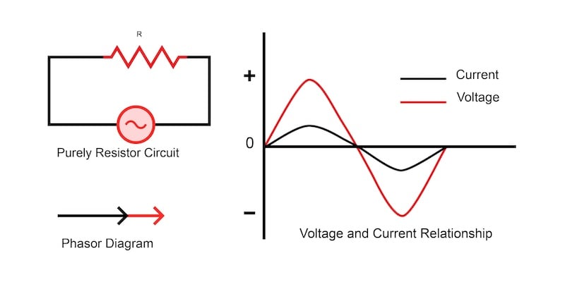
Figure 2. Purely Resistive Load Circuit, Phasor Diagram, and Voltage and Current Waveform Relationship. Image used courtesy of Simon Mugo
The current and voltage waveform are almost identical. They both pass their minimum and maximum point and finally pass the zero axis at the same point in time. This is an indication that the system has a power factor of 1.
The phasor diagram shows that both the current and the voltage are in parallel, and this tells us all the energy taken by the system is utilized (and in the case of the electric resistor) to create heat. The purely resistive system is said to have a unity power factor.
Purely Inductive Load
A good example of such a system is an induction motor. The circuit, the curves, and the phasor diagram for the system are shown in Figure 3 below.

Figure 3. Purely Inductive Load Circuit, Phasor Diagram, and Voltage and Current Waveform Relationship. Image used courtesy of Simon Mugo
An inductive load such as a motor has a coil that contains a magnetic field that holds back current resulting in a phase shift where voltages and currents waveforms end up being out of sync, making a current pass through the zero point after the voltage has already passed. The outcome of the waveforms is called the lagging factor.
Reactive power is not that important, but a little of it is needed to maintain the electromagnetic effect of the motor so that it can enable the motor to rotate. The reactive power becomes a waste when we cannot utilize it but still pay for it.
On the phasor diagram, the current line is at an angle but below the voltage line. This implies that not all the consumed electricity is utilized by the inductive system.
Pure Capacitive Load
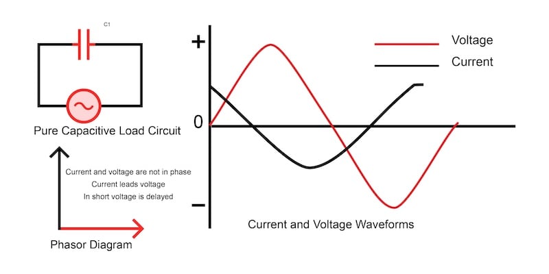
Figure 4. Purely Capacitive Load Circuit, Phasor Diagram, and Voltage and Current Waveform Relationship. Image used courtesy of Simon Mugo
For the capacitive load, the opposite of the inductive load discussed above will happen. The current and voltages will be out of phase, but this time, voltage instead of current is held back. The resultant effect is a leading power factor. Again, this implies we are not using all the electricity to perform work, but we will end up dishing out cash to clear its bill.
On the phasor diagram, the current line is at an angle and above the voltage line since it is leading.
How to Correct Power Factor
The most common problem encountered is the lagging power factor. For poor power factor correction, capacitors and sometimes inductors must be added to the circuit system. The capacitors and the inductors will help realign the voltage and the current into the required phase and convert the power factor to one or closer.
When the problem is due to a lagging power factor, which is brought about by high inductive loads, then capacitors can solve the problem. When the problem is a leading power factor caused by high capacitive loads, inductors must be added to the circuit system to solve it.
Don’t add capacitors and inductors blindly into the system. You need to calculate them, and we will do that at the end of the article.
Reason for Fixing Poor Power Factor
Poor power factor means the system is drawing more power from the source for it to do the same quantity of work, and therefore, a larger cable is needed. This will increase the cost of electrical installation more than usual.
When a power factor is too low, expect a penalty charge or a reactive power charge from the electric company.
Sometimes poor power factor causes losses in equipment, for example, transformers, due to high heat gains associated with it. It also leads to voltage drop, which interferes with the life expectancy of some equipment.
Calculating Capacitance for Power Factor Correction
As indicated earlier, we shall end the article by looking at how to calculate the capacitance needed to correct the poor power factor in a building setup. Let’s look at the practical example below.
Problem
A building in Nairobi City has a power supply of 415 V with a total electrical load of 70 kW. The building’s electrical system has a power factor of 0.76, but according to power supply authorities, the building should have a power factor of 0.97 for the owner to avoid penalty charges if found in violation. Calculate the capacitance needed to correct the power factor from 0.76 to 0.97.
Solution
\[Total\_Apparent\_Power(kVA)=\frac{True\_Power(kW)}{PF}PF=0.76,\,True\,Power70kW\]
\[Therefore, Apparent\_Power=\frac{70kW}{0.76}=92.11kVA\]
\[The\,Total\_Reactive\_Power(kVAr)=\sqrt{Total\_Apparent\_power(kVA)^{2}-True\_Power(kW)^{2}}\]
\[The\,Total\_Reactive\_Power(kVAr)=\sqrt{92.11^{2}-70^{2}}\]
\[=59.87kVAr\]
\[Targeted\_Total\_Apparent\_Power=\frac{70}{0.97}=72.16kVA\]
\[The\,Targeted\_Total\_Reactive\_Power=\sqrt{72.16^{2}-70^{2}}=17.52kVAr\]
\[Capacitor\_Size=Total\_Reactive\_Power-Targeted\_Total\_Reactive\_Power\]
\[Capacitor\_Size=59.87 - 17.52=42.35kVAr\]
Key Takeaways of Power Factor
- Power factor is a ratio of true power to apparent power.
- There exist good, bad, and poor power factors with specific ranges where 1.0 to 0.95 is said to be good, 0.95 to 0.85 poor, and 0.85 and below is said to be bad.
- When the system achieves a power factor of 1.0, the system is approved to be perfect.
- Poor power factor originates from a system's resistive, inductive, and capacitive loads.
- Lagging power factor is the most likely problem an engineer will encounter regularly.
- A balance of capacitors and inductors in the systems solves the problem of poor power factor.
- It is important to fix poor power factors to avoid high power bills, increase the life of equipment, and reduce the cost of electricity installation associated with it.
- Formulas exist to determine the power factor, apparent power, reactive power, true power, and capacitance needed to solve problems around the power factor.