Facebook
 Google
 GitHub
 Linkedin
PFC Control Methods Overview
Power factor correction (PFC) is needed for AC-DC power supplies with input power greater than 75 W. This article offers an overview of the most popular PFC control methods.
This article is published by EEPower as part of an exclusive digital content partnership with Bodo’s Power Systems.
Power factor correction (PFC) is required for an AC-DC power supply with input power greater than 75 W, as it forces the input current to follow the input voltage such that the electronics load appears to be a pure resistor. Many different PFC control methods have been developed, each has its pros and cons, and different PFC topologies may use different control methods.

Image used courtesy of Adobe Stock
Constant TON Control
This control method is used in critical conduction mode (CRM) PFC. It has no current loop; the voltage loop output determines the boost switch turn on time (TON). When the boost switch turns off, the inductor current drops. Once inductor current drops to zero, boost switch turns on again, as shown in Figure 1.
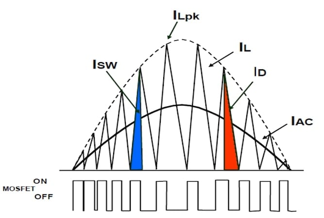
Figure 1. Inductor current waveform in CRM PFC. Image used courtesy of Bodo’s Power Systems [PDF]
Equation 1 expresses the average current value in each switching cycle:
\[I_{AVG}\frac{I_{LPK}}{2}=\frac{V_{IN}*T_{ON}}{2L}\,\,\,(1)\]
In steady state, the voltage loop output is constant; therefore, TON is constant, then inductor current is proportional to VIN. If VIN is sinusoidal, the inductor current will be sinusoidal, achieving a good power factor.
CRM PFC is widely used in low power applications. It is simple, low cost and easy to implement. But because there is no current loop, the total harmonic distortion (THD) is not as good as average current-mode control. For high-power applications, you would need to interleave two or more phases to reduce the current ripple.
Average current-mode control with shunt sensing
This control method is used in continuous conduction mode (CCM) PFC. As shown in Figure 2, a shunt (RS) in the PFC ground return path senses the inductor current. A current reference (IREF) is generated through three components: A (the voltage loop output), B (VIN_rms2), and C (rectified VIN). Since A and B are constant in steady state, VIN modulates IREF. If VIN is sinusoidal, IREF is sinusoidal. The current controller (GI ) forces IIN to follow IREF, achieving a good power factor.
CCM PFC is popular in high-power applications from a few hundred watts to a few thousand watts. Compared to constant TON control, average current-mode control has lower THD, a better power factor, and easier electromagnetic interference filter design given the constant switching frequency and lower current ripple. The control is more complex, however, and the larger boost inductance results in a larger inductor size.
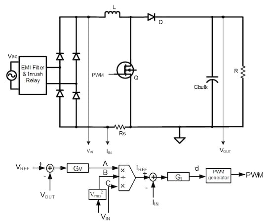
Figure 2. An average current-mode controller. Image used courtesy of Bodo’s Power Systems [PDF]
Average Current-Mode Control with CT Sensing
Not all CCM PFC can use shunt sensing. In interleaved PFC, in order to balance the input current for each phase, each phase current needs individual sensing. Putting a shunt on the PFC ground return path is not applicable, since it senses the total current. Similarly, in dual-boost semi-bridgeless PFC, part of the inductor current will return through the inactive phase; putting a shunt on the PFC ground return path does not obtain the total current information.
In both cases, you can put a current transformer (CT) in series with the boost switch to sense the switching current of each phase. Because the switching current is only part of the total inductor current, a common practice is to sense the current at the middle of TON, as shown in Figure 3; use Equation 2 [1] to convert the required average IREF into an instantaneous IREF' at the middle of TON; and then use IREF' to replace IREF in the average current-mode controller shown in Figure 2.
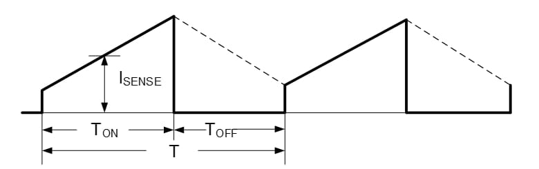
Figure 3. Sensing at the middle of TON. Image used courtesy of Bodo’s Power Systems [PDF]
\[I_{REF^{'}}=\frac{I_{REF}*T(V_{OUT}-V_{IN})}{T_{ON}*V_{OUT}}\,\,\,(2)\]
Average Current-Mode Control with Bidirectional Current Sensing
For AC switching bridgeless PFC and totem-pole bridgeless PFC, where the inductor current is bidirectional, shunt sensing is also not applicable, a bidirectional current sensor such as Hall-effect sensor is needed. With sinusoidal input current, the Hall-effect sensor output is a sine wave plus a DC offset (Figure 4); therefore, the Hall-effect sensor output cannot be used directly in the average current-mode controller shown in Figure 2.
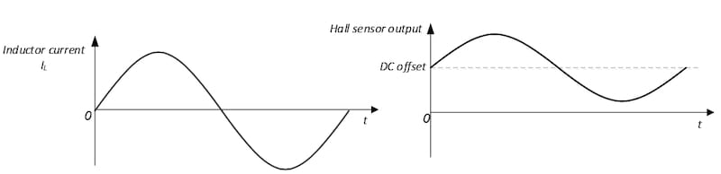
Figure 4. Hall-effect sensor output waveform. Image used courtesy of Bodo’s Power Systems [PDF]
Follow these steps to close the loop:
1. Sense the AC line and AC neutral voltage separately; then use the line voltage to subtract the neutral voltage to obtain a sinusoidal VIN.
2. Calculate the sinusoidal current reference IREF, using the same method as shown in Figure 2.
3. Use the Hall-effect sensor output to subtract DC offset as feedback signal IIN.
4. During the positive AC cycle, the control loop has negative feedback control. See Equation 3
\[Error=I_{REF}-I_{IN}\,\,\,(3)\]
5. During the negative AC cycle, the higher the inductor current, the lower the value of the Hall-effect sensor output; thus, the control loop needs to change from negative feedback to positive feedback, as expressed by Equation 4:
\[Error=I_{IN}-I_{REF}\,\,\,(4)\]
Duty ratio feedforward control THD requirements are becoming more and more strict, reducing THD necessitates pushing the control-loop bandwidth higher and higher. But high bandwidths reduce phase margin, resulting in loop instability. A limited PFC switching frequency also prevents bandwidths from going very high. To address this problem, you can add a precalculated feedforward duty ratio (dFF) to the control loop, as shown in Figure 5.
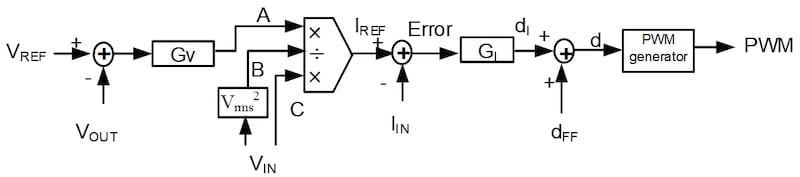
Figure 5. Duty ratio feedforward control. Image used courtesy of Bodo’s Power Systems [PDF]
Equation 5 calculates dFF as:
\[d_{FF}-\frac{V_{OUT}-V_{IN}}{V_{OUT}}\,\,\,(5)\]
The majority control effort comes from dFF, as the current loop compensator changes the duty ratio around this calculated duty ratio pattern. Since the impedance of the boost inductor at the line frequency is very low, a small variation in the duty ratio produces enough voltage across the inductor to generate the required sinusoidal current waveform so that the current loop compensator does not need to have a high bandwidth. This control method is suitable for applications where low THD is required but controller has a limited bandwidth.
No VIN Modulation Control
The above-mentioned control methods all rely on a current reference generated through VIN modulation. In this control method, no need VIN modulator, therefore no need VIN sensing. The measured input current is compared with a saw-wave VRAMP. The amplitude of VRAMP is proportional to the voltage loop output. The pulse-width modulation output signal always starts low at the beginning of the switching cycle and stays low until VRAMP rises linearly to intersect IIN. The VRAMP and IIN intersection determines the switch turnoff time (TOFF), as shown in Figure 6.
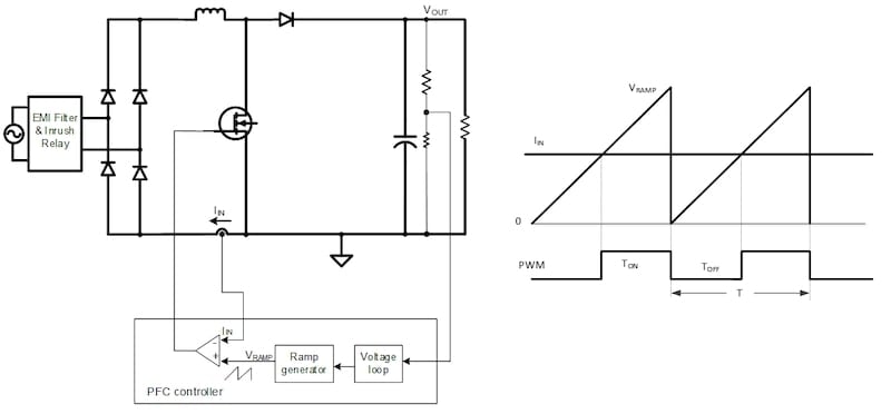
Figure 6. No VIN modulation control. Image used courtesy of Bodo’s Power Systems [PDF]
Equation 6 [2] derives the input current as:
\[I_{IN}=V_{IN}*\frac{V_{RAMP}}{V_{OUT}}\,\,\,(6)\]
Both VOUT and VRAMP are constant in steady state. Thus, IIN is solely proportional to VIN. If VIN is sinusoidal, IIN is sinusoidal, achieving a good power factor.
Compensation is very easy for this control method, making its implementation straightforward. On the other hand, Equation 6 is based on CCM, it is not valid any more when PFC enters discontinuous conduction mode (DCM), therefore the THD is not as good as average current-mode control shown in Figure 2. Moreover, no VIN sensing means no VIN brown out protection. This control method is suitable for applications where VIN brown out protection is not required.
Peak Current-Mode Control
Peak current-mode control is popular in DC/DC converters, but it is not suitable for PFC because PFC needs to control the average current. But through the use of a special PWM generator, as shown in Figure 7, peak current-mode control becomes possible for PFC [3]. In Figure 7, the sensed switching current IQ is compared with a saw wave. Equation 7 determines the saw-wave peak voltage (VRAMP).
VRAMP starts at the beginning of each switching period, and linearly drops to 0V at the end of the switching period. The boost switch (Q) turns on at the beginning of the switching period. Q turns off when I Q exceeds the saw wave.
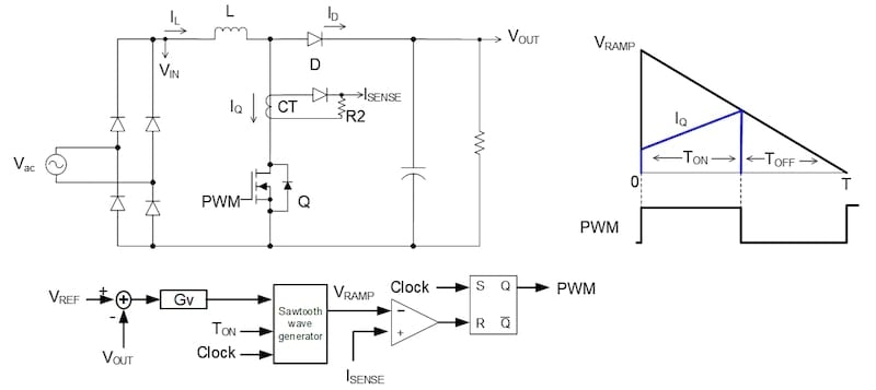
Figure 7. Peak current-mode control. Image used courtesy of Bodo’s Power Systems [PDF]
\[V_{RAMP}=G_{v}*V_{OUT}+\frac{T_{ON}*V_{OUT}*R}{2*L}\,\,\,(7)\]
Equation 8 derives the average current as:
\[I_{AVG}=\frac{G_{v}}{R}*V_{IN}\,\,\,(8)\]
In Equation 8, Gv is the PFC voltage loop output. It is constant in steady state; therefore, IAVG is proportional to VIN. If VIN is sinusoidal, IAVG is sinusoidal, achieving a good power factor.
Compared to average current-mode control, peak current-mode control eliminates the error amplifier, multiplier, compensation network and input voltage sensing circuit, resulting in lower system costs. The power losses caused by the CT are also less than the current shunt resistor. Since a higher current ripple is then acceptable, it is possible to reduce the boost inductance; thus, you can use a smaller-sized boost inductor to increase the power density and reduce costs. This control method is suitable for a low-cost combo control solution, because it does not need to sense VIN and CT itself provides isolation, then the controller can be put on the secondary side of DC/DC converter and combining with DC/DC controller to make a combo controller.
Multimode Control
- CRM/DCM control for CRM PFC. For CRM PFC, the switching frequency is variable; the lighter the load, the higher the switching frequency. A high switching frequency results in high switching losses. To improve light-load efficiency, let the PFC operates in CRM at full load and transitions seamlessly into DCM [4] with a reduced switching frequency at a reduced load, as shown in Figure 8. CRM/DCM multimode operation provides excellent efficiency over a wide load range, is suitable for applications requiring high light-load efficiency.
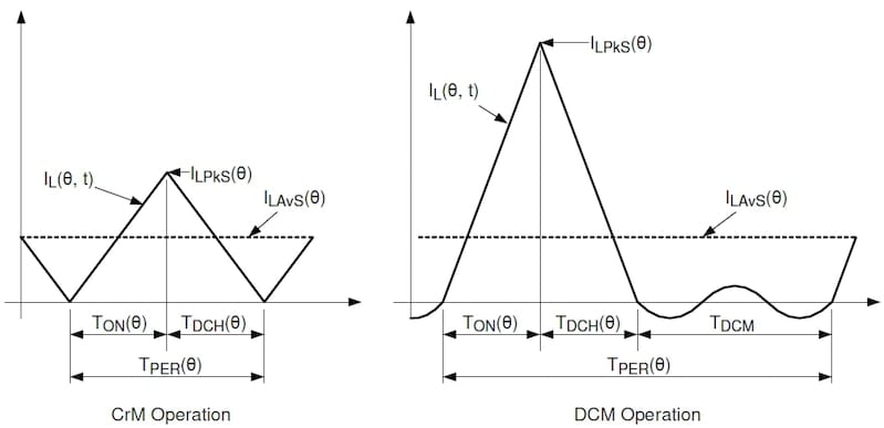
Figure 8. CRM/DCM operation. Image used courtesy of Bodo’s Power Systems [PDF]
- CCM/CRM control for CCM PFC For CCM PFC, the inductor current drops to zero before the end of the switching cycle at light loads, and PFC enters DCM. The switching losses are still high in DCM. To reduce switching losses, let PFC operates at CRM with zero voltage switching (ZVS) or valley switching at light loads, and switches back to CCM at heavy loads. This CCM/CRM operation not only improves light-load efficiency, but also reduces current spikes at the boundary between CCM and DCM [5], is suitable for applications requiring high lightload efficiency and low THD.
- CCM/TCM control for totem-pole bridgeless PFC Totem-pole bridgeless PFC can operate in CCM or triangular current mode (TCM); each has its advantages and disadvantages. To improve overall performance, let the PFC operates at CCM at heavy loads or at AC peak, and operates at TCM with ZVS at light loads or around AC zero crossing, as shown in Figure 9. This type of multimode operation combines the advantages of both CCM and TCM operations, very suitable for applications requiring both high-efficiency and high-power-density [6].
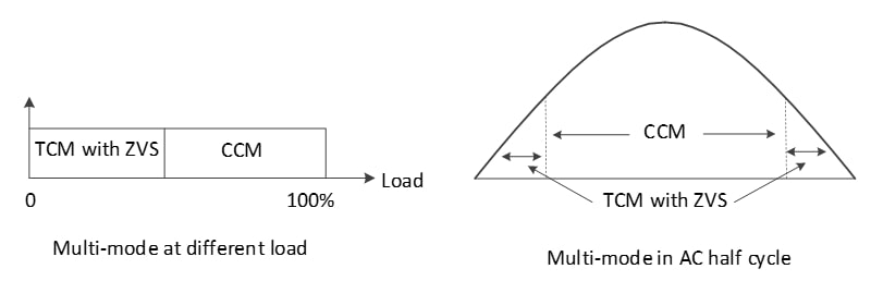
Figure 9. CCM/TCM operation. Image used courtesy of Bodo’s Power Systems [PDF]
References
[1] “Digital current balancing for an interleaved boost PFC”, Texas Instruments Analog Design Journal, 2013.
[2] UCC28180 datasheet, Texas Instruments.
[3] “Power factor correction using peak current-mode control,” Texas Instruments Analog Design Journal, 2023.
[4] UCC28056 datasheet, Texas Instruments.
[5] “PFC THD Reduction and Efficiency Improvement by ZVS or Valley Switching,” Texas Instruments Application note, 2012.
[6] “A Multi Mode Control Algorithm for Totem Pole Bridgeless PFC,” 2025 IEEE Applied Power Electronics Conference and Exposition (APEC), Atlanta, Georgia, 2025.
This article originally appeared in Bodo’s Power Systems [PDF] magazine.