Facebook
 Google
 GitHub
 Linkedin
Measuring Power Using AC Wattmeters
The wattmeter is a combination of an ammeter and a voltmeter. It measures both voltage and current and determines the resultant power.
Electric power is measured using an instrument called a wattmeter. The wattmeter comprises two coils–one for current and the other for voltage.
Power Dissipation
Heat is dissipated when an electric current flows in a conductor due to work done in moving electrons past atoms. Work is also performed in a lamp filament when the electric current is converted into light. Similarly, work is done when a speaker converts electric current into sound and when an electric motor produces motion.
The time rate of doing work is Power (P).
If a certain amount of work (W) is done in a time (t), then P=W/t. It can be demonstrated that the power supplied to any electrical component is:
\[Power=Current\times Voltage\]
Or
\(P=EI\) (1)
The watt (W) is the unit of electric power.
When an applied potential difference of 1 V causes a current of 1 A to flow in a circuit or device, the power supplied is
\[P=EI=1V\times1A=1W\]
From Ohm's Law,
\[E=IR\,and\,R=\frac{E}{I}\]
Substituting for I in Equation (1) gives
\[P=\frac{E}{R}\times E\]
Or
\(P=\frac{E^{2}}{R}\) (2)
And substituting for E in Equation (1) gives
\[P=I\times IR\]
Or
\(P=I^{2}R\) (3)
From Equations 1, 2, and 3, it is seen that power can be calculated from a knowledge of any two of E, I, and R.
Electric heating elements convert electricity into heat for boiling water, space heating, etc. As illustrated in Figures 1 (a) and (b), power supplied to an electric lamp is converted into light, and a speaker converts input power into sound. The instrument employed for measuring power is called a wattmeter.

a. The power dissipated in a lamp is converted into light.
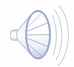
b. Power supplied to a speaker is converted into sound.
Figures 1 a and b. Power is dissipated when an electric current flows. Power can be converted into light, heat, sound, and mechanical motion. Image used courtesy of Amna Ahmad
AC Power Measurement
The dynamometer instrument can be employed as a voltmeter or ammeter or, in its major application, as a wattmeter. Consider the illustrations in Figure 2 that show the field coil and moving coil of a dynamometer instrument connected in series. With current flowing in the direction shown in Figure 2(a), the field coils set up fluxes with N poles on the right-hand side and S poles on the left-hand side. Also, the moving-coil flux has the polarity illustrated, S at the bottom and N at the top. The N pole of the moving-coil flux is repelled from the adjacent N pole of the field coil flux, and the two adjacent S poles also repel each other.
The moving coil is deflected clockwise, causing the pointer to move over the scale from left to right.
Now consider the effect of reversing the direction of the current through the coils. As illustrated in Figure 2(b), the field coil fluxes are now S on the right-hand side and N on the left-hand side. The moving-coil flux is also reversed, having S at the top and N at the bottom. Once again, like poles are adjacent to each other, and the pointer moves from left to right over the scale.
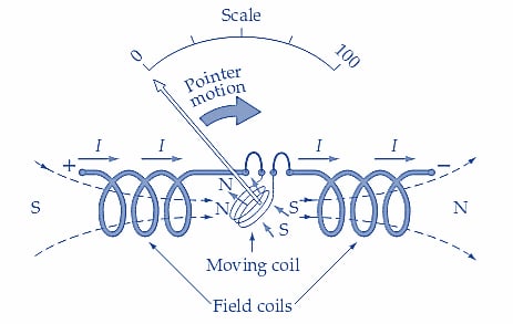
a. Current flowing from left to right produces a positive deflection
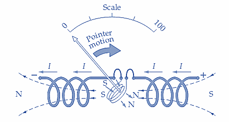
b. Current flowing from right to left produces a positive deflection
Figures 2 a and b. When the current flow through a dynamometer instrument reverses, both the field flux and the moving-coil flux reverse directions. The pointer deflection is unaffected. This makes the instrument suitable for application to AC measurements, as well as DC measurements. Image used courtesy of Amna Ahmad
It is seen that the dynamometer instrument has a positive deflection, regardless of the direction of the current through the meter. The meter terminals are not marked positive (+) or negative (-); the dynamometer instrument is un-polarized. So, the instrument gives a positive deflection when either direct or alternating current flows through the coils. As an ammeter, the instrument's scale can be read as direct current when measuring DC and as the rms value of alternating current when measuring ac. Similarly, as a voltmeter, the dynamometer instrument indicates DC volts or rms AC volts. The instrument's scale can be calibrated on DC and then used to measure AC.
For AC and DC, the major application of the dynamometer instrument is as a wattmeter.
As illustrated in Figure 3(a), the connection for measuring AC power is similar to that for measuring power in a DC circuit. The input terminals of the voltage and current coils are identified with a ±, ↓, or * sign. The marked terminal of the current coil should be connected to the supply, and the voltage coil marked terminal connected to the load side of the current coil. In alternating-current applications, the load current could lead or lag the load voltage by a phase angle (ϕ). The instrument deflection is proportional to the in-phase components of current and voltage. Thus, as shown in Figure 3(b), the instrument indication is proportional to EI cosϕ. The true power dissipated in a load with an AC supply is P =EI cosϕ. So, when used as an AC wattmeter, the dynamometer instrument measures the true power supplied to the load.
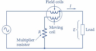
a. Dynamometer instrument as an AC wattmeter
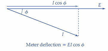
b. Phasor diagram of load current and voltage
Figure 3. The deflection of the pointer on a dynamometer wattmeter is proportional to EI cosϕ, so the instrument measures true AC power. Image used courtesy of Amna Ahmad
Example 1
A wattmeter measures the AC power delivered to a load as 100 W, and an ammeter and voltmeter indicate that the load current and voltage are 1.5 A and 100 V, respectively. Calculate the phase angle between the current and voltage.
Solution
\[True\,Power=P=EIcosφ\]
So,
\[cosφ=\frac{P}{EI}=\frac{100W}{100V\times1.5A}=0.667\]
And,
\[φ=cos^{-1}(0.667)=48.2°\]
Example 2
A 115 V source supplies 700 mA to a load. If the power supplied to the load is measured as 75 W, determine the phase angle between the load current and the supply voltage.
Solution
\[cosφ=\frac{P}{EI}=\frac{75W}{115V\times100mA}=0.932\]
And,
\[φ=cos^{-1}(0.932)=21.3°\]
Key Takeaways–AC Wattmeters
Electric power can be measured with test instruments such as wattmeters, power quality meters, and clamp-on ammeters. A wattmeter is a test instrument to measure true power in a circuit. A wattmeter is provided with a scale that is usually graduated in watts (W), kilowatts (kW), or megawatts (MW). A wattmeter is used to analyze circuits by measuring the true power. Depending on the system connections (whether a Wye-connected or Delta-connected), several wattmeters can be used to measure true power in a three-phase system.
Featured image used courtesy of Adobe Stock