 Facebook
 Google
 GitHub
 Linkedin
What Is Wye And Delta?
Voltage, Current, Energy, and Power
We learned in a previous page that resistors can be connected in series or in parallel. Sometimes, circuit analysis is easier if we convert series or parallel resistors into a single equivalent resistor. However, resistors can be configured in a way that does not result in a series connection or a parallel connection:
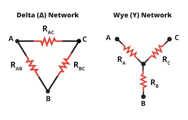
Figure 1. Delta and wye networks
These two resistor configurations cannot be reduced to a single equivalent resistance. They are called delta and wye (or Y) networks, because of their shapes. They can also be arranged as pi (π) and T networks. It’s important to recognize that in terms of electrical behavior, the delta network is exactly the same as the pi network and the wye network is exactly the same as the T network; they are merely drawn differently.
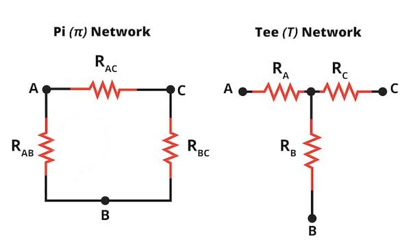
Figure 2. Pi and T networks (the names come from their appearance) are alternative ways of drawing delta and wye networks.
Three-Phase Power
Delta and wye networks are used in conjunction with three-phase power (as you will see below, the delta configuration is also found in a bridge rectifier circuit). Most people are accustomed to the single-phase AC power that is delivered to homes, but three-phase AC is used extensively in distribution systems and for powering industrial equipment. It is called “three-phase” because it consists of three sinusoidal voltages; these voltages have the same amplitude and frequency, but they are 120° out of phase relative to one another.
A three-phase arrangement is more efficient compared to a single-phase implementation because the three-phase system can deliver more power relative to the weight of the conductors. Three-phase power is also advantageous because the amount of instantaneous power available from the system is constant. The instantaneous power delivered by single-phase AC varies according to the sinusoidal nature of the supply voltage, but with three-phase AC, the amplitude variations in one of the three voltages are balanced by the phase-shifted variations in the other two voltages.
Delta and wye configurations enable a circuit to present an equal, or balanced, load to all three phases. An important difference between the delta configuration and the wye configuration is the number of nodes: the delta has three (i.e., one node for each phase), and the wye has four. The fourth node in the wye network allows for the connection of a neutral wire. A neutral wire must be available if one of the phases is going to be used to power equipment that runs on single-phase AC.
Delta-Wye Conversions
It is possible to convert a delta network into a functionally equivalent wye network, and it is also possible to convert a wye network into a functionally equivalent delta network. “Functionally equivalent” means that the overall electrical behavior of the converted network is identical to the overall electrical behavior of the original network. In other words, if the original network is connected to the system at terminals A, B, and C, we can remove the original network and connect the converted network to terminals A, B, and C without changing the behavior of the system.
At this point we know what a delta–wye conversion is, but we don’t know why someone would want to perform these conversions. It turns out that converting a delta network to a wye network, or a wye network to a delta network, can facilitate the analysis of a larger circuit that includes a delta or wye network. In the next section we’ll look at the conversion formulas, then we’ll work through an example.
Delta-Wye Conversion Formulas
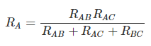
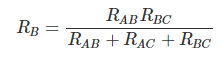
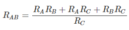
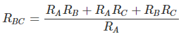
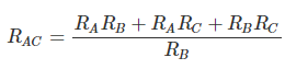
The following formulas allow you to calculate wye-network resistances from delta-network resistances.
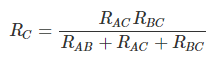
To calculate delta-network resistances from wye-network resistances, we use these formulas:
An Example
Consider the following circuit:
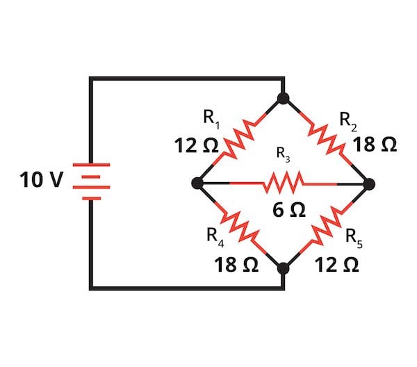
Figure 3. R1, R2, and R3 form a delta configuration
Looks pretty tough, but the astute reader will recognize R1, R2, and R3 as forming a delta configuration. Now, the fun begins!
First, let’s change the resistor labels so that we can directly use the conversion formulas.
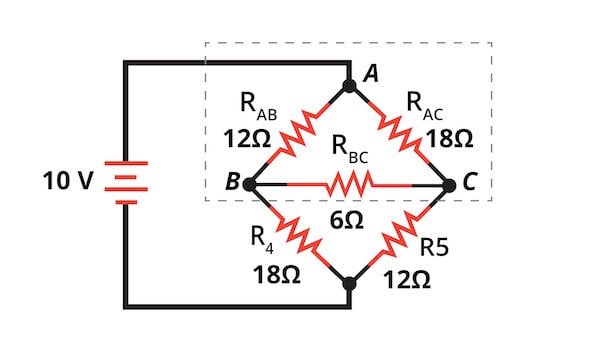
Figure 4. Updated resistor labels
Now, we can convert the delta configuration composed of RAB, RAC, and RBC to a wye configuration.
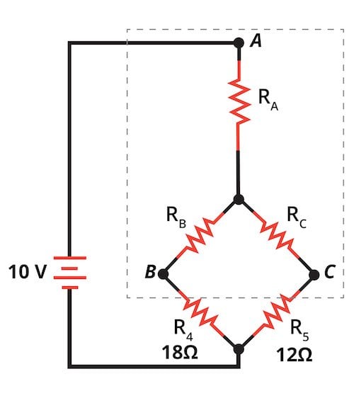
Figure 5. Convert the delta configuration to a wye configuration
Using the formulas from the previous section, we can find RA, RB, and RC for our wye network.
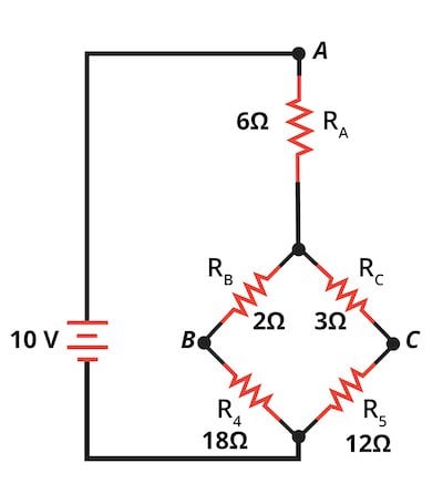
Figure 6. RA, RB, and RC for the wye network
RB and R4 are series resistors with an equivalent resistance of 20Ω, and RC and R5 have an equivalent resistance of 15Ω. These two equivalent resistances are in parallel, so the overall equivalent resistance of RB, RC, R4, and R5 can be calculated and added to RA. We now have an equivalent resistance for the entire group of resistors, and since we know the voltage across this equivalent resistance, we can use Ohm’s law to find the current through RA. This current allows us to determine, through simple but lengthy calculations, the voltages shown in Figure 7.
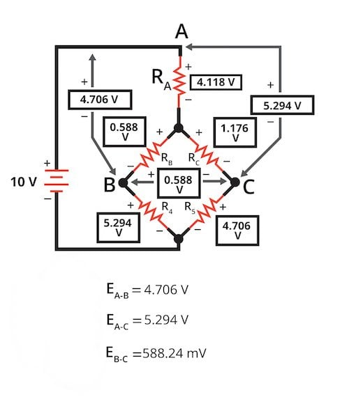
Figure 7. Calculated voltages
Now we can transfer these results to our original delta network, keeping in mind that equivalent networks will produce the same voltages at terminals A, B, and C.
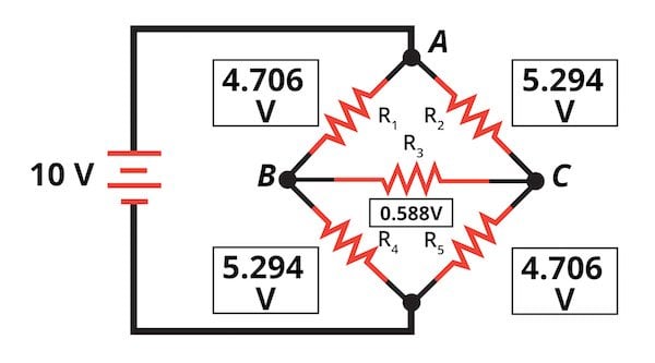
Figure 8. The voltage across each resistor
Figure 8 shows the voltage across each resistor, and now we can use Ohm’s law to find the current flowing through each resistor.
Delta and Wye Networks Review
We discussed three-phase AC power and two circuit configurations—the delta network and the wye network—that are used in three-phase systems. We also looked at the role of delta–wye conversions in circuit analysis.
In the next page, we’ll explore electrical power in the context of AC voltages and currents.