 Facebook
 Google
 GitHub
 Linkedin
Power Factor And RMS Explained
Sinusoidal Steady State Power
In the previous page, we saw that the mathematical representation of AC power can take the following form:
`P(t)=\frac{VI}{2}\cos(\theta)+\frac{VI}{2}\cos(2\omega t-\theta)`
In this page, we’ll discuss the significance of the quantity cos(θ), and we’ll also see how this expression for P(t) is related to the use of RMS values for voltage and current.
The Impedance Angle
We already know that the angle θ indicates the phase difference between voltage and current. It’s important to understand, though, that this same angle appears elsewhere in AC power analysis and plays a prominent role in characterizing an AC system.
The quantity θ is also the angle between resistance and impedance in the impedance triangle.
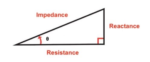
Figure 1. The impedance triangle
As you can see from the diagram, the value of θ is influenced by the circuit’s ratio of reactance to resistance, and this makes sense given the effect of reactance on the phase relationship between voltage and current.
If a circuit is dominated by reactance, the vertical side of the triangle will be much longer than the horizontal side, and thus θ will be close to 90°. This is consistent with what we know about purely reactive circuits: they create a phase difference of 90° between voltage and current.
If a circuit is dominated by resistance, the horizontal side will be much longer than the vertical side. Consequently, the value of θ will be very small, just as there is very little phase shift between voltage and current in a circuit that is almost purely resistive.
As you might recall from Chapter 1, the angle between resistance and impedance in the impedance triangle is the same as the angle between active power and complex power in the power triangle.
We can see, then, that θ originates from the amount of resistance and reactance found in a given circuit, and the mathematical relationship between these two elements extends into sinusoidal phase shift and power behavior.
Power Factor
Now that we’ve discussed the significance of θ itself, we need to recognize the special importance of the cosine of the angle θ. As shown by the expression for P(t), average power dissipation is determined by voltage amplitude, current amplitude, and cos(θ). Average power varies from (V×I)/2 to zero as cos(θ) varies from 1 to zero (corresponding to θ that varies from 0° to +90° or –90°).
It’s not surprising, then, that the cosine of θ—whether you interpret θ as the impedance angle, the angle between active power and complex power, or the phase difference between voltage and current—is called the power factor. We multiply the power factor by (V×I)/2 to determine the amount of average power dissipated by a circuit; also, a power factor closer to zero indicates a larger proportion of reactive power.
RMS Voltages and Currents
The expression for the average power of a DC circuit is P = VI. We now have an equivalent expression for AC circuits: `PAVG = (VI/2)cos(θ)`.
We learned in Chapter 1, though, that there are two more ways to calculate power, both of which are simply the result of combining P = VI with Ohm’s law. We have P = V2/R and P = I2R. We can transfer these alternative expressions into the AC domain if instead of R we use the magnitude of the impedance:
`P_{AVG}=\frac{1}{2}\frac{V^2}{|Z|}\cos(\theta)`
`P_{AVG}=\frac{1}{2}I^2|Z|\cos(\theta)`
These formulas are useful in themselves, but they also give us an opportunity to demonstrate one of the advantages of RMS values. We learned in Chapter 1 that the RMS value of a voltage or current is equal to the peak value divided by the square root of 2.
`V_{RMS}=\frac{V}{\sqrt{2}}`
`I_{RMS}=\frac{I}{\sqrt{2}}`
Notice what happens when we take the square of an RMS value:
`V_{RMS}^2=\frac{V}{\sqrt{2}}\times\frac{V}{\sqrt{2}}=\frac{1}{2}V^2`
`I_{RMS}^2=\frac{I}{\sqrt{2}}\times\frac{I}{\sqrt{2}}=\frac{1}{2}I^2`
Thus, if we use RMS values instead of peak values in the alternative power equations given above, we don’t have to worry about keeping track of the one-half factor:
`P_{AVG}=\frac{V_{RMS}^2}{|Z|}\cos(\theta)`
`P_{AVG}=I_{RMS}^2|Z|\cos(\theta)`
This same simplification applies to the original expression for power:
`P_{AVG}=\frac{1}{2}VI\cos(\theta)=V_{RMS}I_{RMS}\cos(\theta)`
Calculating Power with RMS Values
We learned in Chapter 1 that the RMS value of a voltage or current allows us to directly compare AC power dissipation to DC power dissipation.
A DC voltage, denoted by VDC, will produce a certain amount of power dissipation when applied to a circuit. Let’s say that we want to use an AC signal to drive this same circuit, and we want to maintain the same power dissipation. To accomplish this, the peak value of the AC voltage must be equal to VDC×√2.
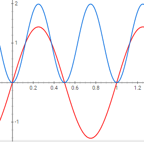
Figure 3. The red waveform represents a current or voltage signal, and the blue waveform is the square of that current or voltage signal. Notice how the peak value of the signal must be equal to 1×√2 (≈1.4) if we want the square of the signal to have an average value of 1. This demonstrates why an AC signal needs to have a peak value of VDC×√2 if the goal is to produce power dissipation equal to what we would obtain by using a DC source with a value of VDC.
If we describe this AC signal using the peak value, we have VAC = VDC×√2. If, instead, we describe it using an RMS value, we have
`V_{AC(RMS)}=\frac{V_{AC}}{\sqrt{2}}=\frac{\sqrt{2}V_{DC}}{\sqrt{2}}=V_{DC}`
We can use one of the equations given above to confirm that an AC voltage or current with an RMS value of x (where x stands for any specific number) is equivalent, in terms of power dissipation, to a DC voltage or current with an amplitude of x. We already know that
`P_{AVG}=\frac{V_{RMS}^2}{|Z|}\cos(\theta)`
If we assume that this is a purely resistive circuit, |Z| becomes R and cos(θ) equals 1. So for a purely resistive circuit that is driven by an AC voltage, we have
`P_{AVG}=\frac{V_{RMS}^2}{R}`
If a resistive circuit is driven by an unvarying DC voltage with an amplitude of VDC, the average power (and the instantaneous power) is
`P_{AVG}=\frac{V_{DC}^2}{R}`
Thus, if PAVG hasn’t changed and R hasn’t changed, VDC must be equal to VRMS.
Review
We’ve discussed two important topics related to the long-term power dissipation of AC systems, and we’ve connected both of these concepts back to the mathematical expression for time-varying AC power. In the next page we’ll deepen our understanding of power factor by working through an example of power factor correction.
Thank you for your valuable and precise notes. Crystal clear explanation. Keep rocking.