Facebook
 Google
 GitHub
 Linkedin
Power Factor Correction: Reactive Power Compensation Methods
This article introduces power factor correction, why it is needed, and how to design it for the system.
Increasing photovoltaic penetration tied to the grid has caused many problems for utility providers. One of the main problems is that most of the power electronics used consume reactive power, which causes low power factor and system instability–a problem that has put power factor correction methods under development again. This article discusses the two most used reactive power compensation methods.
Power Factor
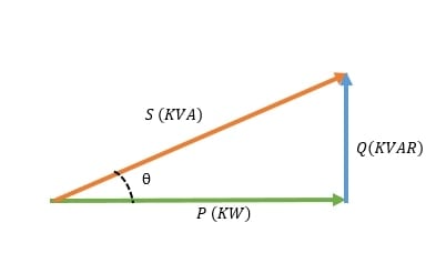
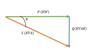
The electric power used to run an appliance is called demand power or apparent power expressed in Volt-Ampere (S). The apparent power is a combination of two powers, true power expressed in Watt (P) and reactive power expressed in VAR (Q).
\[S^{2}(KVA)=P^{2}(KW)+Q^{2}(KVAR)\]
The relation between the power types.
Power factor determines the system's power efficiency and is the ratio between true power and apparent power. The lower the power factor, the less efficient a power system is. The power factor lags with inductive load and leads with capacitive load. Resistive loads have a unity power factor.
(a)
(b)
Figure 1. (a)-the power factor expresses as cosθ leading power factor. (b)-lagging power factor. Image used courtesy of Ahmad Ezzeddine
Power Factor Correction
Power factor correction drives power factor to unity. The importance behind power factor correction lies within the effects of having a low power factor on energy prices, instrument lifetime, and accessory sizing, such as electrical cables.
Generally, induction machines used in industrial factories running at low loads, arc lamps, and varying power usages at short intervals cause a low lagging power factor. Therefore, utilities charge those factories using a power factor or maximum demand tariff (KVA tariff).
Machines, conductors, and electrical accessories running at low power factor will have overheating problems due to that lower lifetime. With all this in mind, utilities and consumers seek a way to ensure power factor is close to unity.
The principle of Power Factor Correction
All power factor improvement methods lay under the same principle. For every load with a lagging power factor, a load with a leading power factor must be connected in parallel to ensure a power factor close to unity.
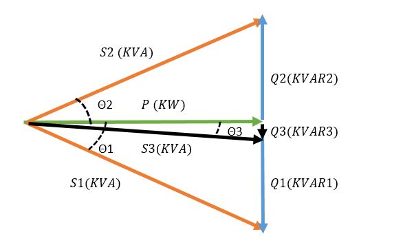
Figure 2. In this diagram, S1 is the power of a load Q1 is the lagging reactive power and cosθ1 is the power factor. Introducing a leading load with Q2 as reactive power causes the formation of S3, the power for the formed system, Q3 minimized lagging reactive power and cosθ3, an overall power factor after correction closer to a unity power factor at P. Image used courtesy of Ahmad Ezzeddine
The equation relating to the image above is
\[Q3 = Q1-Q2=P*(tan(\Theta1)-tan(\Theta2))\]
Power Factor Correction Methods
There are several methods used for power factor correction. The 2 most used are capacitor banks and synchronous condensers.
1. Capacitor Banks:
- Capacitor banks are systems that contain several capacitors used to store energy and generate reactive power. Capacitor banks might be connected in a delta connection or a star(wye) connection.
- Power capacitors are rated by the amount of reactive power they can generate. The rating used for the power of capacitors is KVAR. Since the SI unit for a capacitor is farad, an equation is used to convert from the capacitance in farad to equivalent reactive power in KVAR.
In the equation below, C is the capacitance in microfarads, V is the voltage in volts, and f is the frequency in hertz
\[KVAR=C*2\Pi*f*V^{2}*10^{-9}\]
- Capacitor banks are designed to operate in stages. Since capacitors have a leading power factor, and reactive power is not a constant power, designing a capacitor bank must consider different reactive power needs. For example, the configuration for a 5-stage capacitor bank with a 170 KVAR maximum reactive power rating could be 1:1:1:1:1, meaning 5*34 KVAR or 1:2:2:4:8 with 1 as 10 KVAR. The stepping of stages and their number is set according to how much reactive power changes in a system.
- Capacitor bank systems have other elements, such as protection components: contactors and switch disconnectors, HRC fuses, and circuit breakers. Also, capacitor banks need an enclosure to protect them from overheating, dust, and water.
- Detuning reactors are connected to capacitor banks in series to deal with voltage and current distortions.
- Discharge resistors are also used for each capacitor to discharge it after being disconnected from the supply in a relatively short time interval.
- To calculate the maximum discharge resistance, a ratio between the maximum discharge time approved by IEC60831 and a logarithmic capacitor charging must be applied.
Maximum Discharge Resistance = Maximum Discharge Time / (⅓ Capacitance* log (√2*Line Voltage / Capacitor Discharge Voltage))
- Capacitor banks not only create a stable system but cause lower KVAH consumption and have a good payback period even when neglecting maintenance and life costs of appliances running at low power factor.
Comparing two 60 kW systems running at 0.6 pf for 10 hours a day. The first system has no power factor improvement system, and the second has a capacitor bank connected in parallel with the appliances correcting the power factor to unity.
The yearly bill will be: total demand * operating hours * 365 * unit price
The total demand for the first system will be: (60(KW)/(0.6 pf))* 10 *365 * unit price per KVAH= 365000 unit price.
The total demand of the second system will be: 60*10*365 * unit price per KVAH= 219000 unit price.
The total improvement in the yearly bill will be: 365000-219000= 146000 unit price
Note: Interest rates, maintenance and operation costs, and other factors were ignored. The calculations above are used to simplify and show how power factor correction could change energy bills.
2. Synchronous Condensers:
- Synchronous condensers are simply over-excited synchronous motors running at no load. When connected in parallel with the loads, a synchronous condenser generates the needed reactive power for the system.
- The sizing of a synchronous condenser is proportional to the amount of reactive power that might be consumed by the electrical system.
- A synchronous motor runs at three different states. Underexited, intermediate excited, and overexcited. The states change with the change of excitation current. Under Excited synchronous motors act as an inductive load, therefore, consuming reactive power. Intermediate excited motors act as a resistive load, therefore, having no reactive power consumption or generation. Over-excited state, at this state current sine wave leads the voltage, therefore, generating reactive power at a leading power factor.
- In the phasor diagram below V is the voltage of the system and θ2 is the angle between the voltage and the load current. Cosθ2 is the lagging power factor showing that the system is consuming reactive power. A synchronous motor is added in parallel with the load and runs without loading the shaft.
Applying a large excitation current to the motor creates an over-excited state of the motor, therefore, producing cosθ1, a leading power factor. At this stage, the synchronous motor is generating reactive power and supplying it to the system
The resultant of the system is the vector summation of the load current and motor absorbed current, resulting in new current with an angle from system voltage θ3, cosθ3 is the resultant power factor of the system closer to a unity power factor.
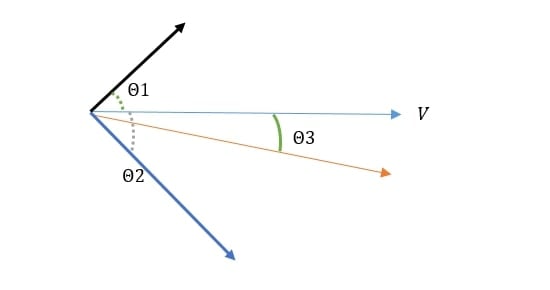
Figure 3. Phasor diagram representing adding an overexcited synchronous condenser to a lagging load. Image used courtesy of Ahmad Ezzeddine
- Synchronous condensers use an automatic excitation controller to measure the power factor of the system and operate at the required state. For example, a synchronous condenser is connected in parallel with a load of 50 kVAR reactive power. The synchronous motor will be over-excited to reach a 50 KVAR reactive power generation. Another load operating at 37.5 KVAR is connected to the system, then the control unit of the synchronous condenser will increase its excitation current until it covers the extra 37.5 KVAR.
- To calculate the reactive power(Q) generated by a synchronous condenser, consider the internal machine voltage Ei and the terminal phase voltage Ep.
Q= 3Ep * (Ei - Ep) /Xd. Where Xd is the synchronous motor reactance.
- The advantage of synchronous condensers over capacitor banks is that they could generate the exact amount of reactive power needed. Whereas a capacitor bank will generate the total reactive power of the nearest stage to the load.
- With the recent huge penetration of renewable energy into the grid, power factor and voltage stability became a concern for utility operators. So, synchronous condensers are becoming the modern topic of research. A lot of research is ongoing regarding virtual synchronous machines. Moreover, new methods of implementing synchronous condensers to different positions on the grid are being studied.
Capacitor Banks vs. Synchronous Condensers
Capacitor banks and synchronous condensers might be used for similar applications. But, usually, capacitor banks are used in factories and low-capacity substations. Synchronous condensers are most feasible with high powers above 200 MVA stations and HVDC converter stations.
Table 1. Capacitor Banks vs. Synchronous Condensers
|
|
Capacitor Banks |
Synchronous Condensers |
|
Life Time |
Short (Up to 10 years) |
Long (Up to 25 years) |
|
Power Factor Adjustment |
Inaccurate and Complex Operation (Stepping) |
Stepless and Simple Control (Excitation Control) |
|
Maintenance Cost |
Low (no mechanical operation) |
High |
|
Fault Recovery |
Changing spoiled capacitors is not a feasible suggestion |
Faults are easily removed |
|
Power Losses |
Very low |
Relatively high |
|
Installation |
Easy installation(Lightweight and does not require foundation) |
Complex (Heavy Weight, needs a starting mechanism and foundation). |
Featured image used courtesy of Adobe Stock