Facebook
 Google
 GitHub
 Linkedin
Switching Performance of 750A/3300V Dual SiC-Modules
This article focuses on the switching behavior of SiC devices and compares Full SiC and Hybrid SiC with the behavior of a silicon device.
Generally, the emerging SiC technology is associated with very high switching frequencies resulting in compact converters This article focuses on this switching behavior of SiC devices and compares Full SiC and Hybrid SiC with the behavior of a silicon device. All considered modules are rated for 3.3 kV and similar current ranges to give a fair and illustrative comparison. Finally, the article gives an outlook on future higher-voltage 6.5 kV SiC technology.
The Development of 3.3 kV Full and Hybrid SiC Modules
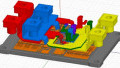
Since the 1990s, Mitsubishi Electric has researched and developed semiconductor devices made of silicon carbide (SiC) [1]. The development of 3.3 kV devices, including the full SiC module, finished in 2017. This 3.3 kV Full SiC module uses the most recent dual package, the LV100, and is rated for 750 A (Figure 1).

Figure 1. 3.3 kV / 750 A Full SiC module in the LV100 package
For increasing blocking voltages, the electrical resistance of MOSFETs increases steadily. Therefore, Silicon (Si) MOSFETs are usually available up to 600 V. For higher voltage levels, Si-based semiconductors require the use of bipolar devices, which are able to reduce the on-state voltage by conductivity modulation. Therefore, high-voltage Si devices are usually bipolar IGBTs and PiN diodes.
Owing to the higher dielectric breakdown, SiC may use unipolar MOSFETs and Schottky Barrier Diodes (SBDs) even at high voltage levels. The advantage of unipolar devices is the absence of charge carrier accumulation. Hence, these unipolar devices switch faster and have lower switching loss compared to their bipolar counterparts.
In this article, a comparison of the switching behavior of bipolar Si devices and unipolar SiC devices, all rated for 3.3 kV and similar current ratings, is shown. The measurements demonstrate the nature of these two different semiconductors regarding their switching performance.
Switching Performance of Full SiC
Recently, Mitsubishi Electric released its LV100 package. This package is regarded as an additional standard package for high voltage power modules. The advantages include an easy parallel connection and high power densities (per heat sink area). Moreover, the module contains a half-bridge phase leg and is designed for low-inductive connection of the DC link—features mandatory for utilizing the full potential of fast-switching SiC. In a similar LV100 package, Mitsubishi Electric offers semiconductor made of Si and SiC. Also a SiC hybrid module is available, which utilizes a bipolar Si IGBT together with a unipolar SiC diode. These three modules are compared in Figures 2 and 3.

Figure 2. Turn-ON waveforms (Vcc = 1800 V, IC = 600A, Tj = 150 °C, Ls = 65 nH

Figure 3. Turn-OFF waveforms (Vcc = 1800 V, IC = 600A, Tj = 150 °C, Ls = 65 nH)
Figure 2 (a-c) show the turn-ON waveforms of the Si, Hybrid SiC and Full SiC modules respectively. While the active devices (IGBT or MOSFET) turn ON, the corresponding free-wheeling diodes are turned OFF. If this is a Si diode, a reverse-recovery current is generated which also flows through the active devices. This reverse recovery current appears as current peak during turn ON, as observed in Figure 2 (a). In case the freewheeling diode is made of SiC, like in the Hybrid SiC module, this current peak almost disappears (see Figure 2 (b)). This results in a reduction of turn-ON energy Eon by 38%. Using a Full SiC MOSFET and utilizing steeper voltage transients further reduces the turn-ON energy by an additional 32%. Moreover, the reverse recovery energy loss Erec in the diode for the Hybrid SiC and Full SiC is zero.
Analogously, Figure 3 (a-c) shows the switching waveforms during turn-OFF. The waveforms at turn-off for Si and Hybrid-SiC are the same and, consequently, turn-OFF energy of both modules are the same. In fact, in both cases, the same IGBT is turned OFF and the turn-OFF behavior is independent of the diode. The use of Full-SiC, however, reduces the turn-OFF losses due to the absence of the tail current and the increased switching speed. In the measurement, a reduction of 87% is achieved. Of course, this reduction of switching loss implies fast voltage transients. The performance at lower switching speeds is discussed in reference [2].

(a) Turn-OFF, Tj =25°C

(b) Turn-OFF, Tj =150°C

(a) Turn-ON, Tj =25°C

(b) Turn-ON, Tj =150°C
Figure 4: Full SiC switching waveforms for different junction temperatures = 65 nH) (Vcc = 1800 V, IC = 750A, Ls = 65 nH, [250 A/div; 500 V/div; 1 μs/div])
Reverse recovery and tail currents of Si devices usually show significant temperature dependency. Consequently, switching losses increase with higher chip temperature. In SiC devices, this effect is less pronounced. As shown in Figure 4, switching behavior at Tj = 25°C and Tj = 150°C is quite similar. The switching-loss change at a nominal current between 25°C and 150°C is only about 10%.
Reduction of Switching Losses
After explaining the physical background for the lower switching losses, the impact over the operating range is discussed in more detail. Figure 5 shows the total switching energy, meaning the sum of turn-ON, turn-OFF and recovery energy loss, for different switching currents. As discussed before the switching energy loss decreases significantly using SiC. To put in numbers, compared to Si, the switching energy loss reduces for Hybrid SiC and Full SiC by 50% and 80% respectively at 600 A.

Figure 5. Switching losses (Eon+Eoff+Err) for each 3.3 kV semiconductor technology (Vcc = 1800 V, Tj = 150 °C, Ls = 65 nH)
Due to the lower switching energy loss, SiC technology allows higher switching frequencies. Figure 6 shows the ratio of switching frequency achieved by SiC versus Si considering same switching losses. Consequently, Hybrid SiC achieves about twice as high switching frequencies (at nominal current) compared to Si.

Figure 6. Switching frequency compared to Si device for equal switching losses (Vcc = 1800 V, Tj = 150 °C, Ls = 65 nH)
Furthermore, Full SiC reaches about 5-times higher switching frequencies at the same switching current. Comparing this to a PWM application and considering the conduction loss, a 5-9 times higher switching frequency can be expected [3].
The higher switching frequency brings advances in many applications. Often filters, transformers or machines can be design more compact, which again increases the system efficiency and reduces costs.
Finally, it is worth mentioning that these modules are intended for critical applications that have the highest quality and reliability requirements, like railway traction drives. The development of the 3.3 kV Full SiC module is finished and same or higher reliability is achieved compared to classical Si traction modules. Moreover, Mitsubishi Electric holds many years of field experience with 3.3 kV SiC technology in railway applications. Therefore, 3.3 kV SiC has become a major and reliable technology.
Future Technology
A well-known effect in SiC semiconductors is the so-called “bipolar degradation” or “stacking fault expansion”. These terms describe a dislocation of the SiC lattice evoked by the recombination of the electron-hole pairs as a result of bipolar currents [4] [5]. Ultimately, this effect leads to an irreversible degradation causing an increasing forward voltage drop. The SBD freewheeling diode, connected in anti-parallel to the MOSFET, prevents the SiC MOSFET from bipolar current and bipolar degradation respectively.
Today’s 3.3 kV SiC modules successfully use separate SBD chips, connected inside the module next to the MOSFET chips. Nevertheless, considering even higher voltage levels like 6.5 kV Full SiC MOSFETs, this approach is no longer economical. Therefore, Mitsubishi Electric has developed a technology to embed the SBD diode inside the MOSFET chip, instead of using separate chips [6]. Figure 7 illustrates the conventional and enhanced MOSFET chip structure.

Figure 7. SBD-embedded MOSFET structure to optimize protection against bipolar degradation for 6.5 kV SiC MOSFETS
This technology is able to shrink the totally required SiC chip area to make SiC technology more efficient and more economical at voltage ratings above 3.3 kV [7].
3.3 kV Full SiC and Hybrid SiC Power Module Characteristics
This article has shown the switching characteristics of state-of-the-art 3.3 kV Full SiC and Hybrid SiC power modules. It has been explained that due to the nature of unipolar SiC devices, switching losses reduce by 50 – 80 %. As a result, Full SiC can operate at 5-times higher switching frequency. In today’s 3.3 kV SiC technology, the SBD diode chips inside the power module effectively protect the MOSFET from bipolar degradation. Now, Mitsubishi Electric has developed the SBD-embedded MOSFET, which is a key enabling technology for efficient and economical higher-voltage SiC technology.
About the Authors
Nils Soltau received the Diploma degree in electrical engineering and information technology from RWTH Aachen University, Aachen, Germany, in 2010.,Since March 2010, he has been with the Institute for Power Generation and Storage Systems (PGS), E.ON Energy Research Center, RWTH Aachen University, where he builds up a 5 MW dc–dc converter. His research interests include high-power dc–dc converters, medium-voltage power semiconductors, and magnetic components.
Eugen Wiesner is an Application Engineer at Mitsubishi Electric Europe B.V., Ratingen Germany, one of the branches of the Japanese multinational electronics and electrical equipment company, Mitsubishi Electric Corporation. He earned his Master's of Science in Electrical Engineering at the University of Applied Sciences Dusseldorf located in Germany.
Kenji Hatori works as an Assistant Manager on Project Management at the Mitsubishi Electric Corporation, Fukuoka Japan, a branch of the Japanese multinational electronics and electrical equipment company, Mitsubishi Electric Corporation, that specializes in power device works.
This article originally appeared in the Bodo’s Power Systems magazine.