Facebook
 Google
 GitHub
 Linkedin
Confronting Power Converter Performance Challenges
This article discusses power converter performance challenges and how to mitigate them.
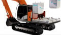
Several technical fields of study, including electrified transportation, renewable energy, and smart grids, use power electronic converters extensively. Power converter performance is challenged by the rapid development of these areas, necessitating the creation of smaller, lighter, and more effective converters. To accomplish these objectives, researchers first optimize various factors to boost converters' performance.

EVs, renewable energy, and smart grids use power electronic converters extensively. Image used courtesy of Adobe Stock
Power Converter Performance Challenges
Selecting the best semiconductor chips, ensuring the best circuit layout, designing a heat dissipation structure, and so on are done. In addition to these factors, manufacturing techniques are important. Rapid prototyping serves as a basis for verifying the design, and choosing the right manufacturing process may ensure the design plan is implemented quickly and successfully. Additionally, advanced manufacturing has an impact on how items are configured.
Pros and Cons of Automated Manufacturing Technology
Over the past ten years, research and development have gone into advanced assembly and manufacturing techniques for power electrical device production, including additive manufacturing (AM), automatic feeding, soldering, and packaging. Utilizing these advanced methods opens up a new opportunity for creating power electronic components with complex structures and small sizes.
Advantages
AM technologies make it simpler to manufacture power circuits with complex internal structures and greater performance. Due to its ease of manufacture, flexibility in structural design, and speedy prototyping time compared to conventional manufacturing techniques like mold casting, punching, and mechanical machining, AM has generated a lot of interest in power converters. This method has steadily been adopted in producing various power components and converters over the past few years.
The availability of new printable materials, improved printing accuracy, and reduced costs are advantages of this technique. For instance, a power inverter with a 3D-printed heat sink was developed by researchers at the Oak Ridge National Laboratory (ORNL) at the beginning of 2014. With AM technology, more complicated shapes may be explored, waste can be reduced, and heat transfer efficiency can be improved, leading to smaller packages.
The adoption of AM also enhances power electronics in other ways. For example, AM allows more freedom to optimize the winding geometric shape, such as windings with different cross-sectional profiles, to reduce power losses in a particular operating mode compared to a traditional wire winding method where the winding cross-sectional shape is mostly constrained. It has precise control over the components' self-resonance frequency and operating bandwidth by precisely reproducing the intended winding structure and parasitic capacitance.
Disadvantages
Despite the benefits, AM has several disadvantages compared to conventional techniques. The main problem is that traditional treatment outperforms AM regarding material characteristics. For instance, the International Annealed Copper Standard (IACS) has found that 3D-printed PCB is just 5–30% as conductive as copper. Because the devices must always be operated under high current and high power circumstances, this restricts the use of AM.
Autonomous and Automated Assembly in Power Converters
PCB assembly is the most crucial of the industry’s current autonomous and automated assembly and manufacturing techniques.

Figure 1. Typical PCB assembly process. Image used courtesy of IEEE Journal of Emerging and Selected Topics in Power Electronics
Figure 1 depicts a typical double-layer PCB assembly procedure. The manufacturers may select several manual or automated methods, depending on the volume, complexity, and time required for each operation on their assembly lines.
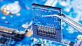
Pick-and-place machines or collect-and-place devices are typically used to assemble surface mount devices (SMDs). Surface mount technology (SMT) is the name of the automated procedure. SMDs have smaller packages than through-hole (TH) components while maintaining the same performance, and their package design makes them suitable for automated manufacture. Auto assembly is more competitive for SMDs because manual assembly is more difficult due to the small size of SMDs.
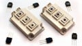
Theoretically, if only SMDs are employed in the products, automation can be fully realized. However, TH devices are frequently incorporated into power converter designs, and their automatic assembly has sometimes been complicated. Axial lead color band resistors, radial lead power capacitors and inductors, and TH discrete devices, including MOSFETs and insulated gate bipolar transistors (IGBTs), are the main components of TH devices used in power converters, as seen in Figure 2.

Figure 2. Various TH components (a) Axial lead type (b) and (c) Radial lead type (d) TH package. Image used courtesy of IEEE Journal of Emerging and Selected Topics in Power Electronics
Depending on the kind of components that will be put together, different machines can be utilized for automatic TH assembly. The axial lead component insertion procedure is the main emphasis of the initial stages of automatic assembly, as depicted in Figure 3. The various kinds of TH parts can also be automatically put into the holes with further advancements in TH technology. If a lead diameter is very similar to that of the hole during automated TH insertion, it may increase the fault rate of the inserting process.
Therefore, the manufacturers select methods that are appropriate for their production.
Under specific circumstances, such as considering the dimension difference between leads and holes, avoiding improperly inserted components, or employing SMDs to alternate axial TH elements, complete automation of power converter manufacturing is feasible.

Figure 3. Automatic insertion of axial lead components (a) Tape feed (b) Shearing leads (c) Forming leads (d) Inserting. Image used courtesy of IEEE Journal of Emerging and Selected Topics in Power Electronics
Soldering
The TH components are typically soldered via wave soldering. SMDs are protected by solder pallets during the wave soldering procedure, as depicted in Figure 1, to prevent exposure to the molten solder. Products with high yields gain a lot from this approach. However, the small production volume makes it inadequate for designing and producing SMD protection fixtures. Glue dispensing devices are typically employed to overcome this problem by placing adhesive dots to hold SMDs onto the PCB in wave soldering since the melting point of the glue is higher than that of the solder.
In addition to some independent dispensing machines developed to replace screen printing, some automatic adhesive dispensers are integrated into pick-and-place equipment, allowing the deposition of adhesive and solder paste on the PCBs without the need for solder masks. On the other hand, gadgets glued to the PCB are difficult to repair because they cannot be simply removed. Other compensation procedures may be used to address this issue.
For instance, the selective soldering method can replace wave soldering, allowing each TH pin to be individually connected using mini-wave soldering. By doing this, glue is not required to hold SMDs in place during a subsequent wave soldering operation. Robotic arms can also offer PCB assembly that is more automated and intelligent. For instance, soldering robots are frequently used for soldering each pin of TH components automatically. According to their heating method, there are primarily two types of soldering robots.
First, a laser can melt the solder wire at the soldering spot. The second type is tip soldering, in which an electrically operated arm uses an electric iron to melt the solder wire at the pin position. These two types of soldering techniques are shown in Figure 4. The laser beam heats the lead and solder without a soldering iron, and any contact between the iron tip and components close to the soldering pins helps smaller joints be soldered with less interference from adjacent components.

Figure 4. (a) Laser soldering method (b) Contact soldering method. Image used courtesy of IEEE Journal of Emerging and Selected Topics in Power Electronics
By combining a component insertion robot and a laser soldering robot into one device, the Japan Unix company has created an integrated soldering system. Figure 5 depicts the physical product image and a schematic for two robotic arms. The robot on the lower side is used to pick up parts. After a vision camera has measured the quality and pin placements, the components are placed into the desired position. The upper-side robot then completes the soldering procedure.
Laser welding can weld a pin in around one second. The approach can be applied to various PCB assembly applications since the two robots solder the TH components as if they were two human hands. The availability of numerous soldering heads and wires for diverse situations, such as superfine wire for micro soldering, enables the device to match the PCB design specifications' accuracy and component density requirements.

Figure 5. Fully automated TH component soldering system. (a) Schematic. (b) Practical device. Image used courtesy of IEEE Journal of Emerging and Selected Topics in Power Electronics
When a lot of TH components are used in power converters, this PCB assembly method takes much longer than wave soldering. However, the use of TH components is declining as SMT continues to improve, allowing for a larger range of applications. Additionally, procedures like wave soldering and screen printing always produce unnecessary waste. Utilizing the new technology can lower hazardous waste emissions and improve the environment.
Takeaways of Power Converter Performance Challenges
The ability to produce small batches of products has become easier because of automation's ongoing development. Small batches in industrial manufacturing are typically called 100 to 1000 units. Even ten units of a product with several SMD components are better suited for automated manufacture. Before the invention of automatic TH technologies, it was preferable to insert TH capacitors and inductors into products manually, even if there were 1000 of them.
Automation is becoming increasingly accessible to small- and medium-sized businesses thanks to the development of new machinery, which is not just a special advantage for manufacturing large industries. Additionally, the recently created machines provide more versatility for handling diverse component geometries and circuit board configurations. As a result, there will be a simple, quick, automatic, and adaptable method of producing power converters in the future.