Facebook
 Google
 GitHub
 Linkedin
Understanding PV Module Performance Characteristics
This article examines the performance characteristics of PV modules, emphasizing key measurements, factors influencing efficiency, and the importance of maximum power point tracking for optimal performance.
Solar PV cells convert sunlight into electricity, producing around 1 watt in full sunlight. Photovoltaic modules consist of interconnected cells, and their output characteristics are represented in an I-V curve. Parameters like open circuit voltage, short circuit current, and maximum power point are crucial for system design. The efficiency of PV modules is determined by how well they convert solar power to electrical power, influenced by factors like sunlight intensity and cell temperature.

Image used courtesy of Adobe Stock
The principal component of a PV system is the solar cell (Figure 1):

Figure 1. A photovoltaic solar cell. Image used courtesy of Wikimedia Commons
PV cells convert sunlight into direct current (DC) electricity. An average PV solar cell is approximately 1/100 of an inch (¼ mm) and 6 inches (153 mm) across. These cells generate around 1 watt of power in full sunlight at approximately ½ volt DC. Possessing a remarkably long lifespan, they can continue to produce electricity from the sun for 25 years or more.
Photovoltaic modules (Figure 2) are interconnected solar cells designed to generate a specific voltage and current. The module's current output depends on the surface area of the solar cells in the modules.
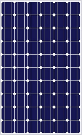
Figure 2. A flat-plate PV module. This module has several PV cells wired in series to produce the desired voltage and current. Image used courtesy of Wikimedia Commons
Output characteristics for a PV module can be found in an I-V curve (Figure 3). An I-V curve represents all the different voltage and current values for a specific module in standard operating conditions. These values are usually based on standard operating conditions of 1000 watts per square meter solar irradiance and cell temperature of 77°F(25°C). The information from a module’s I-V curve is used to rate module performance and to help determine the size of the PV system array.

Figure 3. An I-V curve for a common PV module size. Image used courtesy of Ahmed Sheikh
Open circuit voltage (Voc) is the maximum voltage available when no current is drawn from the module. It determines the maximum circuit voltage for both a module and an array. You can verify the open circuit voltage by allowing sunlight to shine on a module or array and then measure the voltage across the output terminals with a voltmeter. Remember that the voltage is DC, so set your meter accordingly.
The short circuit current (Isc) is the maximum current output of a module under conditions with no resistance (a short circuit). At this point on the I-V curve, the voltage is 0, and the power output is 0. The short circuit current is important for an installer to know because it is used to determine the maximum available circuit currents in the PV system and the size of overcurrent protection devices and system conductors. You can verify the short circuit current by using an ammeter to take the measurement. If the Isc is 10 amps or less, most multimeters that measure amperage can be connected directly across the module leads. Using a multimeter to measure amperage directly in line with a module is safe because the short circuit currents are low. If the Isc is greater than 10 amps, you must use a clamp-on ammeter attachment with a multimeter or a separate clamp-on ammeter. Remember the measured current is DC, so the meters must be set accordingly. Most clamp-on ammeters can only be used on alternating current (AC) circuits.
Maximum power point (MPP) (Pmp) (Pmax) indicates the maximum output of the PV module and is the result of the maximum voltage (Vmp) multiplied by the maximum current (Imp). Maximum power is sometimes referred to as peak power or peak watts. Vmp is the operating voltage when the module’s power output is at maximum. Imp is the operating current when the module’s power output is at maximum. For example, if a module’s Vmp is 25 volts and Imp is 6 amps, the Pmp would be 150 watts.
PV Module Operating Point
The electrical load, or the battery bank if used, determines the operating point of a module on an I-V curve. As seen on an I-V curve, the short circuit current (Isc) is based on 0 ohms load resistance, and the open circuit voltage (Voc) is based on an infinite amount of load resistance. Any point along the module’s I-V curve has a specific load resistance corresponding to a specific operating voltage and operating current. The load resistance value increases as you follow the I-V curve from the left to the right. Use Ohm’s law to find the resistance needed to operate a PV module at any point on the I-V curve.
Solar cells work most efficiently when operating at their maximum power points. Changing temperatures and varying solar irradiance mean the maximum power point changes often. As a result, most installers choose to use equipment in their PV systems that provides maximum power point tracking (MPPT). This feature will maximize PV module performance and is included in most grid-tie inverters and a few charge controllers used in stand-alone systems.
PV Module Efficiency
The efficiency of a PV module is based on how well the incoming solar power is converted to usable electrical power. To find the percent efficiency of an electrical machine like a motor, divide the output power by the input power and then multiply by 100. For example, if a 1HP electric motor has an input of 1800 watts and an output of 1500 watts, the motor’s efficiency would be 83.3 percent:
\[\frac{1500\,Watts}{1800\,Watts}\times100=83.3\%\]
The efficiency of a PV module (or array) is found in much the same way. Solar irradiance is multiplied by the area of the module (or array) to get the solar power in watts. It is then divided into the maximum power output of the module (or array). For example, a PV module with 1.5 square meters of area and a maximum power output of 170 watts is exposed to 1000 watts of solar irradiance per square meter. The module’s percent efficiency is 11.3 percent:
\[\Bigg(\frac{170\,Watts}{1.5m^{2}\times1000\frac{W}{m^{2}}}\Bigg)\times100=11.3\%\]
Effect of Sunlight Intensity
A PV module’s current output is proportional to the intensity of the solar radiation (Figure 4). More intense light equals a greater module output, while less intense light equals a smaller one. The I-V curve remains the same as sunlight intensity drops, but it moves downward, indicating a lower current and power output. However, the voltage changes little even as the current and total power drop.

Figure 4. The current output of this 12 VDC nominal module decreases as the available solar irradiance decreases. Voltage changes very little. Image used courtesy of Ahmed Sheikh
PV Module Cell Temperature
When the temperature of a module’s cells warms above the standard operating temperature of 77°F(25°C), the module operates less efficiently, and the voltage decreases (Figure 5). The I-V curve remains the same as cell temperature increases above 77°F(25°C), but it moves toward the left, indicating a lower voltage and power output. However, the current does not change much even as the voltage and total power drop. Airflow under and over the modules is critical to help keep the cell temperature as low as possible.

Figure 5. The voltage of this 12 VDC nominal module decreases as the cell temperature rises. The current output changes very little. Image used courtesy of Ahmed Sheikh
Remember that a PV module’s wattage rating is based on 1000 W/m2 of solar irradiance at a standard test condition (STC) temperature of 77°F(25°C). However, the module rating must be adjusted because of the high temperatures encountered on roofs or from sunlight heating the modules over several hours. A rating system called PTC (PV USA test conditions) has been developed to account for the normally high module temperatures. The PTC rating is also based on a solar irradiance of 1000W/m2 but uses 68°F(20°C) ambient temperature rather than cell temperature. This means the PTC ratings are about 88 percent of the STC ratings. For example, a 200-watt-rated STC module would have a 176-watt PTC rating. PV system designers often use the PTC ratings to compensate for the reduced performance of modules rated under the STC system.
Harnessing the Full Potential of Photovoltaic Technology
Understanding the performance characteristics and efficiency of PV modules is crucial for effective solar energy utilization. These insights are fundamental for designing solar systems that maximize energy output, considering factors such as sunlight intensity and cell temperature. The knowledge of parameters like open circuit voltage and short circuit current enables proper sizing of overcurrent protection devices and system conductors. Additionally, the incorporation of maximum power point tracking technology enhances the efficiency of PV modules, ensuring optimal energy transfer.
As solar energy becomes more pivotal in sustainable power generation, acquiring expertise in these principles is vital for engineers, installers, and designers to harness the full potential of photovoltaic technology in various applications.