Facebook
 Google
 GitHub
 Linkedin
Switching and Converter Substations
This article explores the various functions of switching and converter substations, including network reconfiguration, fault isolation, and AC/DC power conversion.
The previous article in this 'Types and Functions of Substations' series discussed four types of substations. In this article, we'll discuss two more: switching substations (also known as switchyards) and converter substations. Let's start with switching substations.
Switching Substations
In modern power systems, switching substations like the one in Figure 1 play a critical role in maintaining grid flexibility, operational reliability, and safe fault isolation. Unlike traditional substations that incorporate transformers for voltage conversion, switching substations typically operate at a single voltage level. Instead of voltage conversion, they focus on routing power, sectionalizing networks, and enabling maintenance without disruption.
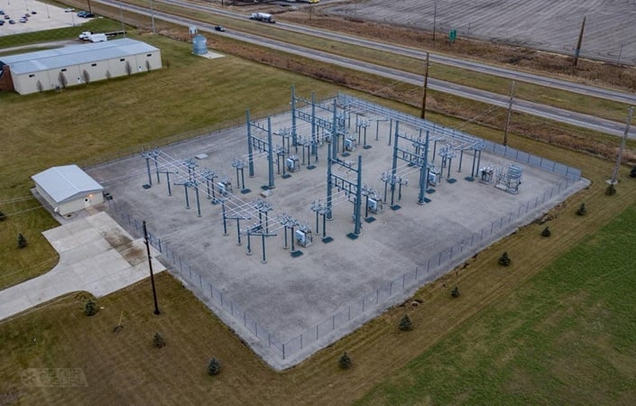
Figure 1. Aerial view of a switching substation. Image used courtesy of the City of Pella
Network Reconfiguration and Switching Dynamics
Switching substations are designed to dynamically reconfigure power flow so that they can respond to changing network needs. These changes might be due to regular maintenance, load balancing, or emergency contingencies. In systems built with a meshed physical topology, reconfiguration through switching allows utilities to optimize power quality, manage loading constraints, and isolate disturbances efficiently.
This flexibility is also a building block for advanced schemes that automate switching actions to quickly restore service following faults, minimizing downtime and improving reliability indices. Fault Location, Isolation, and Service Restoration (FLISR) is an example of this type of capability.
Enhancing Reliability Through Isolation and Adaptive Operation
As previously mentioned, a key function of switching substations is fault isolation—rapidly disconnecting faulty sections to preserve stability and safeguard the remainder of the grid. This involves coordinated operation of circuit breakers, disconnectors, and automated control systems. Moreover, reclosers—fast-acting switches that can automatically reclose after clearing transient faults—are commonly used to reduce outage durations and improve supply continuity.
Effective fault isolation demands selectivity in protection systems: only the faulty zone is disconnected, while the rest of the network remains operational. This requires layered, overlapping protection zones and carefully coordinated relay operations—often using directional or distance relays and pilot protection channels—to avoid unnecessary disconnections.
Technologies such as network protectors further enhance service reliability in dense, secondary-grid urban networks. These devices prevent reverse power flow through transformers during faulted or islanded operation, effectively isolating impacted sections while preserving power from alternate paths.
Switching Substation Configurations
Substation layout is important for reliable switching operations. Common bus arrangements include:
- Ring bus: Offers alternate paths, enhancing reliability even when one breaker is offline.
- Breaker-and-a-half: Balances equipment cost and high operational flexibility.
- Splitter bus or dual bus systems: Ensure continuity by allowing equipment maintenance without full shutdown.
All of the above configurations are meant to facilitate reconfiguration and maintenance. They provide redundancy and sectionalizing capability, both of which are essential for minimizing outage impact during maintenance or fault events.
Switching Substation Functions
In the next section, we'll turn our attention to converter substations. Before that, however, Table 1 summarizes the various functions of switching substations.
Table 1. Functions of switching substations.
| Function | Technical Role |
| Reconfiguration | Adapt topology through switching to manage load, maintenance, and disturbances |
| Fault Isolation | Isolate problem segments fast to maintain system integrity and continuity |
| Service Restoration | Re-route power via automated switching to restore service quickly post-fault |
| Protective Selectivity | Ensure only affected zones open, minimizing service interruption through detailed protection coordination |
Converter Substations
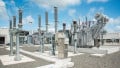
Converter substations (Figure 2) perform the electrical power conversion between alternating and direct current. They also act as power-electronic controllers. Converter substations serve energy-transfer, dynamic support, grid-forming/grid-following, and power-quality functions that cannot be achieved with conventional electromechanical equipment alone.
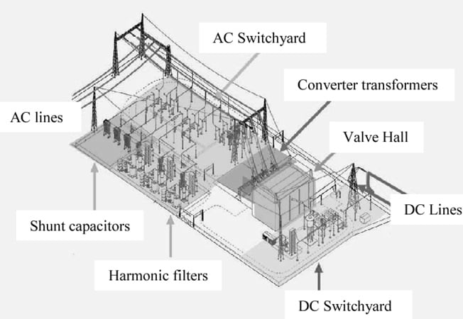
Figure 2. Typical converter substation. Image used courtesy of C. Joe-Uzuegbu
In HVDC transmission, the converter station converts bulk AC power to a controlled DC link for long-distance or asynchronous transfer. A remote station then inverts the DC back to AC. In FACTS applications, the converters are used to synthesize controllable AC voltages or series voltages/currents that provide fast active/reactive power and impedance control at transmission nodes.
Converter Technologies
Two main families of high-power converters are used in these substations:
- Line-commutated converters (LCCs).
- Voltage-source converters (VSCs).
LCCs use series-commutated thyristors or similar line-commutated devices. They rely on the AC system voltage for commutation. Though efficient for very large power transfers and high voltages, they require a relatively strong AC system with sufficient short-circuit level protection. Typically, LCCs also need extensive AC-side filtering and reactive support.
LCC stations are optimized for high continuous power and low losses. However, they have limited ability to independently control reactive power.
VSCs use self-commutated switching devices (IGBTs, IGCTs, etc.) arranged in two-level, three-level, or modular multilevel converters (MMC). VSC-HVDC can independently and rapidly control active and reactive power at each terminal, connect weak or passive networks, provide black-start capability, and embed STATCOM-like functions. The MMC topology in particular offers low harmonic content, modularity, and scalability, making it the preferred architecture for modern VSC-HVDC installations.
Because modern VSCs can synthesize nearly arbitrary three-phase waveforms, they are used for fast damping, power oscillation damping, voltage regulation, and even synthetic inertia in grids with high inverter penetration. VSCs can provide black-start capability and operate effectively in weak-grid conditions. These capabilities are particularly relevant for systems with large shares of renewable generation.
Before we move on, it's worth noting that voltage-sourced converters are the building blocks of many FACTS devices. Two important examples are:
- STATCOM (Static Synchronous Compensator): Controls bus voltage by injecting/absorbing reactive current rapidly. This method is essentially identical to VSC reactive control: regulate the quadrature-axis current or voltage error to produce the desired reactance. STATCOMs are widely applied for voltage support, flicker mitigation, and LVRT compliance at generation interconnections.
- UPFC (Unified Power Flow Controller): Combines a shunt VSC and series VSC connected through a common DC link to control voltage magnitude, series voltage injection (and thus line impedance), and phase angle. The UPFC is the most flexible FACTS device and can realize independent control of active and reactive power on a line, but it is complex and costly.
Principal Hardware Components
A converter substation includes the following key elements:
- Converter transformer(s): Step the AC system voltage to levels suitable for the valve bridge and provide galvanic isolation and phase-shift options (in LCC bridges) used to create multi-pulse operation for harmonic reduction.
- Converter valves/power electronic bridge: Thyristor/IGBT valve assemblies (line-commutated or self-commutated). In MMCs, arrays of submodules form each phase arm.
- Smoothing reactor and DC filter: A DC smoothing reactor stabilizes DC current and limits di/dt; DC filters and active damping reduce harmonics and oscillations on the DC link.
- AC filters and reactive compensation: Especially for LCC installations, large AC filters and capacitor banks are required to meet harmonic standards and supply reactive power; VSCs typically need much smaller passive filtering due to their inherent waveform synthesis.
- Control, protection, and auxiliaries: High-speed digital controls implement current/voltage loops, PLLs, DC-voltage regulation, and station protection and interlocks. Redundant control architectures and high-availability auxiliaries are standard in HVDC plants.
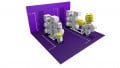
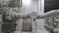
Figures 3 and 4 provide examples of a smoothing reactor and a converter transformer, respectively.
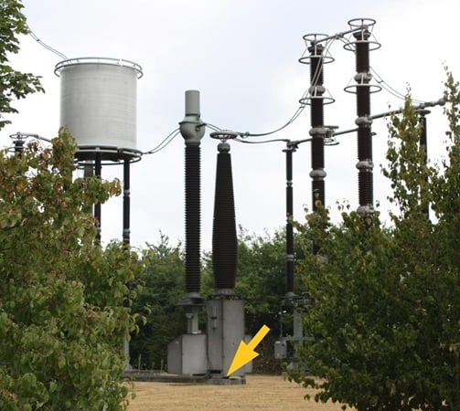
Figure 3. HVDC cable termination and DC smoothing reactor. Image used courtesy of Wikipedia
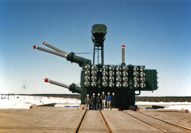
Figure 4. A single-phase, three-winding, converter transformer. Image used courtesy of Wikipedia
Control Objectives and Typical Control Loops
Converter substations implement hierarchical control. Outer supervisory control sets power setpoints, DC voltage reference, ramp profiles, and coordinates converter-to-converter interactions (e.g., one terminal regulating DC voltage while the other regulates active power). In bipole HVDC, one terminal commonly controls active power (P) and the other regulates DC voltage (Vdc) for stable operation.
There is also AC-side power and voltage control. For VSCs, the converter is controlled in a synchronous direct-quadrature (dq) frame using a PLL. In the dq frame, the converter’s instantaneous power expression is:
$$P_{ac}~=~\frac{3}{2}(v_d i_d ~+~v_q i_q)$$
Equation 1.
and its reactive power expression is:
$$Q_{ac}~=~\frac{3}{2}(v_q i_d ~-~v_d i_q)$$
Equation 2.
When vq = 0 (P-control orientation), this simplifies to the widely used control relationships:
$$P_{ac}~\approx~\frac{3}{2}v_d i_d \quad \text{and} \quad Q_{ac}~\approx~-\frac{3}{2}v_d i_q$$
Equation 3.
These relationships form the basis for independently regulating active power (via id) and reactive power (via iq) in VSC controls.
The DC link power balance couples the converters:
$$P_{dc}~=~V_{dc} I_{dc}$$
Equation 4.
with losses such that:
$$P^{(in)}_{dc}~-~P^{(out)}_{dc}~=~Losses_{conv+filters}$$
Equation 5.
In steady state, neglecting losses, active power on the AC sides must match DC power:
$$P_{ac}~\approx~P_{dc}$$
Equation 6.
Therefore, control architectures coordinate AC current references and DC voltage to maintain power flow and limit DC over/under-voltage.
Performance Considerations
Converter substations introduce switching losses, conduction losses, and harmonic injections that require mitigation. Losses depend on topology (LCC vs. VSC), switching frequency, device characteristics, and cooling.
Harmonic performance, thermal limits, converter cooling and valve cooling infrastructure, reactive power requirements, and detailed loss models are key design inputs in HVDC/FACTS project studies and are treated extensively in manufacturer application notes.As well, practical deployment of converter substations must account for the following:
- Grid strength and short-circuit ratio (SCR): LCC requires strong AC systems (high SCR). On the other hand, VSCs tolerate weak systems and can even operate in passive networks.
- Harmonic compliance and filtering footprint: LCC projects commonly require large AC filters and reactive compensation. VSC/MMC designs minimize this need but still require attention to converter-generated harmonics and interaction with passive components.
- Control coordination across terminals: Multi-terminal DC grids, hybrid LCC/VSC schemes, and interaction with AC-side controllers (AVR, PSS) require coordinated control design and stability assessments.
Key Takeaways
In modern power grids, switching and converter substations address distinct but complementary operational needs. Switching substations enhance system flexibility by enabling rapid network reconfiguration, selective fault isolation, and seamless restoration of service—capabilities that directly support reliability and continuity of supply.
Converter substations, on the other hand, provide the essential AC/DC interface for HVDC transmission and FACTS applications, allowing long-distance power transfer, integration of renewable resources, and dynamic control of voltage, power flow, and system stability.
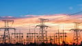
Featured image used courtesy of Adobe Stock