Facebook
 Google
 GitHub
 Linkedin
Precision Cooling of Performance Modules
High power density in electronics necessitates efficient cooling. Learn how passive (heat sinks), forced (cooling aggregates/fans), and liquid cooling methods to maintain prescribed component temperatures and extend lifespan.
This article is published by EEPower as part of an exclusive digital content partnership with Bodo’s Power Systems.
Performance modules and construction components are essential in today’s world of electronics. Constantly increasing power densities in the area of electronics and power electronics absolutely require the implementation of efficient cooling methods. Regardless of the method used, the overarching goal is to operate the functional construction component according to the manufacturer’s prescribed construction component temperature range.
Why is the Cooling of Construction Components Necessary?
The frequent Integration of today’s power semiconductors, such as FET, MOSFET, IGBT, Triac, or SSR, makes cooling these structural components a tricky problem. Power electronics today encompasses everything related to the direction, transformation, or operation of electrical energy. Power electronics starts with a few milliamps of power and a low voltage, but can also mean up to kiloamps and kilovolts. During transformations of currents and voltages, most users are primarily concerned with the efficiency grade of the functional component.
The energy fed into the semiconductor is not completely one hundred percent converted, which means that the resulting losses are radiated away in the form of waste heat. As is well known in Physics there is a direct correlation between temperature stress and the lifetime of electronic building components. Exceeding the maximum operational temperatures stated in the manufacturer's data sheets leads to operational failure, and exceeding the customary temperature parameters can even lead to the destruction of the semiconductor.
As we have just described, the correct cooling of power construction components is enormously important for the functional life of the built-in components, but also for the whole system. Fischer Elektronik offers expert knowledge in the area of building component cooling, as well as offering a selection of efficient and flexible product solutions.
Efficient High-Performance Cooling Units
Passive cooling methods based on the principle of free convection are, from the customer’s perspective, the most frequently demanded for the cooling of power electronics in light of varying marginal conditions. Classic Standard heat sinks, because of their geometry and their assembly, often reach the boundary of their cooling capacity during high power loss situations. High-performance cooling elements (Figure 1) are especially designed for heat dissipation of larger power losses under natural convection, which are seen in most of the highest-capacity heat sink configurations.
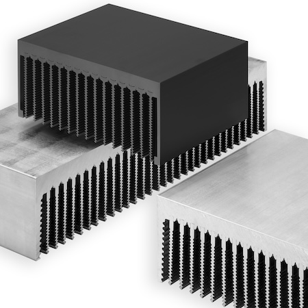
Figure 1. High-performance heat sinks for open convection provide efficient options in order to betterbleed off the loss output in the power electronics. Image used courtesy of Bodo’s Power Systems [PDF]
Because of the complexity and difficulty of manufacture, the assembly of heat sinks consists of two parts. The extrusion process manufacturing of the heat sink base contains a specific press-in geometry that is optionally pressed into various types of fin tubes tailored to customer applications. Furthermore, the massive heat sink base operates as assembly surface for the semiconductor and achieves with a material force of 15 to 20 mm a better heat distribution inside the whole heat sink. To improve the heat transfer resistance under heat exhaust from the fin tubes into the surrounding air, the fin tubes contain a canalization on the top surface that achieves an efficiency improvement of ten percent over that of normal flat tubes.
Should the assembly or the solid mounting of a semiconductor onto the heat sink base be accomplished through the use of a holding thread, the thermal contact may still be compromised by turning the heat sink profile in the opposite direction or by lateral torsion. The level semiconductor assembly surface may only deviate from the heat sink base as an envelope curve by a maximum of 3.6 mm (convex/concave).
Thus, it is relatively easy to anticipate that, for example, high IGBTs, which are often at levels of <0.02 mm according to their manufacturers’ standards, will not be achieved or cannot be made using press-in technology without mechanical refitting. Semiconductor assembly surfaces with outstanding advantages with regard to evenness and roughness can be achieved with an innovative machine fleet and appropriate milling tools that include technical milling through a CNC process (Figure 2).
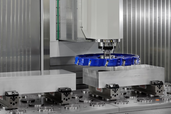
Figure 2. Innovative machinery and suitable operating resources make precise machining of customer-specific heat sink solutions possible. Image used courtesy of Bodo’s Power Systems [PDF]
Air For More Cooling
Should restrictions emerge in the application in terms of geometrical measurements or the associated weight of a high-performance cooling element, or should the efficiency of open convection simply not be adequate to eliminate waste heat, then a significant upgrade of heat dissipation through so-called cooling aggregates is needed. Cooling aggregates operate on the principle of forced convection and possess an inboard, closed thermal exchange structure that is perfectly compatible with the customary fan motors and their performance data in terms of air speed and air volume. Different kinds of cooling aggregates offer a proven thermal technology to power electronics and are, for that matter, when used with customary fan motors, very efficient.
The fan motors with upstream aluminium-treated surfaces generate a strong stream of air that blows over the inboard heat exchange structure in a targeted form. The heat exchange structure discussed here, as a feature of large cooling aggregates, is composed of canalized fin pipes (Figure 3), which result in a larger surface with which to absorb heat. Furthermore, the canalization of the hollow fins increases their functionality as opposed to smooth fins, so that a more turbulent air stream is aimed over the finned surface structure and consequently a more efficient heat transfer from the fins to the passing air stream.
The product group “cooling aggregates” includes special systems such as Segment-, Miniature-, Hollow fin-, or High-performance cooling element-, with axial-, radial, or diagonal fan motors. However, differences in modular superstructures of the cooling aggregates, as well as their technical implementation, are affected by changing operational conditions, electronic building components, and the amount of heat to be dispersed for their optimization. One-sided or double-sided thick base plates ensure a good heat spread inside the fan unit, but serve at the same time as a semiconductor assembly area for the electronic components to be cooled.
Overall, the different types of cooling aggregates are characterized by precisely level milled semiconductor assembly surfaces, streaming-optimized hollow-fin geometry, and lamellar structures for limiting streaming loss, as well as by the capacity to isolate single profile segments both thermally and electrically.
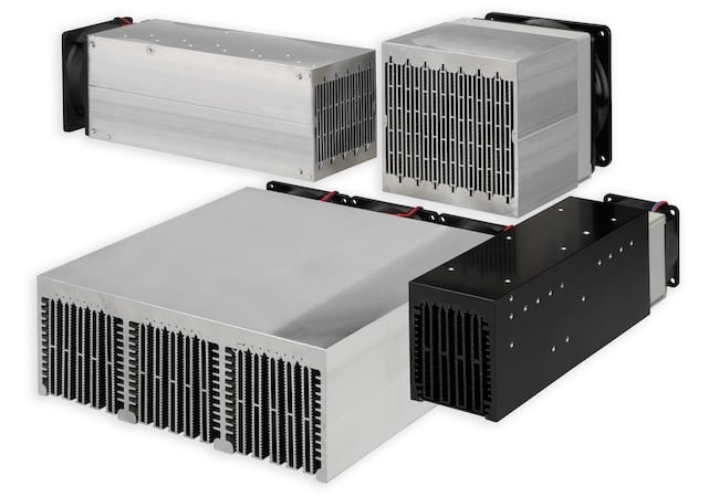
Figure 3. Ventilator aggregates with a fluted hollow ribbed structure, combined with high-performance fan motors, effect considerably higher heat dissipation. Image used courtesy of Bodo’s Power Systems [PDF]
Water and Electronics Working Together
For especially high-performance electronic building components, processing a large volume of heat exchange surfaces for the afore-mentioned high-performance cooling elements can be only conditionally achieved due to the limited heat-spreading effect, the available workspace, the relatively high weight, and the loud noise-generating fan motors, especially if radial fans are being used.
Liquid heat sinks (Figure 4), as a functional alternative cooling concept for the conditions described above, are worth considering for many applications. The popularity of this kind of cooling is, however, still limited and is looked upon in many applications sceptically, even though the problem of compatibility of electronic and water is not really a concern, thanks to the high quality of manufacturing. Special kinds of sealproofing, types of coupling systems, as well as the proven security of hose systems are the reliable hallmarks of today’s technology.
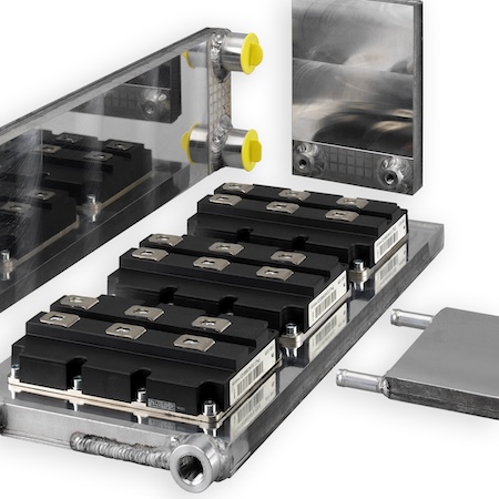
Figure 4. Liquid-based cooling designs provide especially efficient solutions for dissipating the heat from high-loss output in power electronics. Image used courtesy of Bodo’s Power Systems [PDF]
The efficiency of liquid coolers using water as the cooling medium is physically as well as thermally excellent. Assuming the specific heat capacity of water is 4.182 kJ/kg×K, that is, approx. 4 times greater than that of air, liquid cooling is significantly advantageous when compared to other cooling concepts. Another advantage consists of the possibility of a very compact building concept for the elements to be cooled, since, from a construction point of view, liquid coolers require no large heat-spreading surfaces, and the cooling takes place directly on the building component.
The liquid cooling units l- or U- flow-through variants, depending on assembly specifications, are completely finished with Aluminium materials, including the hose connections, and also have an inboard, three-dimensional heat-exchange structure. This offset oppositional lamellar structure is heat conducting surface that is connected to the basis and construction assembly plate and serves for a very good heat transport from the building component to be cooled into the flowing liquid.
This, in turn, creates a homogeneous (horizontal) flow of the liquid cooling sink, and the flow through losses accrued on account of the heat-exchange structure is minimal. The thick mounting plate, which is used for the assembly of the power semiconductor and module, is precisely milled to ensure levelness and allows a free placement of the construction component without constraints. To avoid known pitting corrosion and the associated disintegration of materials, it includes an aluminium material, and the use of corrosion inhibitors is recommended. By standard operation, we recommend a water/glycol mixture in a ratio of 50/50.
This article originally appeared in Bodo’s Power Systems [PDF] magazine.