Facebook
 Google
 GitHub
 Linkedin
Power Quality Monitoring Part 2: Design Considerations for a Standards-Compliant Power Quality Meter
This article explains how to efficiently design a standards-compliant power quality measurement instrument using a ready-to-use platform that accelerates development. It discusses solutions for designing Class A and Class S meters, including a new Class S power quality measurement integrated solution that significantly reduces development time and costs for power quality monitoring products. Part 1 discussed the importance of standards-compliant power quality measurements to provide an understanding of the IEC power quality standard and its parameters.
Part 1 in this series discussed the importance of standards-compliant power quality measurements to provide an understanding of the IEC power quality standard and its parameters. Part 2 explains how to efficiently design a standards-compliant power quality measurement instrument using a ready-to-use platform that accelerates development.
Challenges to Implementing a Power Quality Solution
The basic components of an instrument designed for power quality measurement are shown in Figure 1. First, the current and voltage transducers must account for the operational range of the instrument and adapt the input signal to the dynamics of the analog-to-digital converter (ADC) input. Traditional transducers are the first source of uncertainty in the measurement; therefore, the correct selection is of great importance. Next, the signal goes to an ADC; its individual characteristics, such as offset, gain, and nonlinearity errors, create a second source of uncertainty. Selecting the correct ADC for this function is a demanding effort in designing a power-quality instrument. Finally, a series of signal processing algorithms must be produced to get electrical and power quality measurements from the input signals.

Figure 1. The main components of an instrument for power quality measurements. Image used courtesy of Bodo’s Power Systems [PDF]
Table 1. Accuracy Requirements for Current, Voltage, and Power Measurements Specified by IEC 61000-4-7 Standard
| Class | Measurement | Conditions | Maximum Error |
| A | Voltage |
UM ≥ 1% UNOM UM < 1% UNOM |
±5% UM ±0.05% UNOM |
| Current |
IM ≥ 3% INOM IM < 3% INOM |
±5% IM ±0.15% INOM |
|
| Power |
PM ≥ 150 W PM < 150 W |
±1% PM ±1.5 W |
|
| S | Voltage |
UM ≥ 3% UNOM UM < 3% UNOM |
±5% UM ±0.15% UNOM |
| Current |
IM ≥ 10% INOM IM < 10% INOM |
±5% IM ±0.15% INOM |
Voltage and Current Transducers
Depending on the location and application of the power quality instrument, the nominal supply voltage (UNOM), nominal current (INOM), and frequency vary. Independently of the nominal values that the instrument measures, the IEC 61000-4-7 standard requires power quality measurement instruments to reach the accuracies presented in Table 1; therefore, the transducers must be selected such that the instrument fulfills the accuracy requirements.
INOM: Nominal current range of the measurement instrument
UNOM: Nominal voltage range of the measurement instrument
UM, IM, and PM: Measured values
The IEC61000-4-71 standard recommends designing the input circuitry following these nominal voltages (UNOM) and nominal currents (INOM):
▸ For 50 Hz systems: 66 V, 115 V, 230 V, 400 V, 690 V
▸ For 60 Hz systems: 69 V, 120 V, 240 V, 277 V, 347 V, 480 V, 600 V
▸ 0.1 A, 0.2 A, 0.5 A, 1 A, 2 A, 5 A, 10 A, 20 A, 50 A, 100 A
Additionally, the transducers selected for measuring voltage and current must keep their characteristics and accuracy unchanged when a 1.2× UNOM and INOM are applied continuously. A signal four times the nominal voltage or 1 kV rms, whichever is less, applied for 1 second to the instrument must not lead to any damage. Likewise, a 10× INOM current for 1 second shall not produce any damage.
Analog-to-Digital Converter
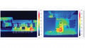
Even though the IEC 61000-4-30 standard does not specify a minimum requirement for sampling rate, the ADC must have enough sampling rate to measure some oscillatory and fast power quality phenomena. An insufficient sampling rate could result in the misclassification of a power quality event or the failure to detect one. The IEC 61000-4-30 standard states that the instrument voltage and current sensors should be appropriate for up to 9 kHz. Thus, the sampling frequency of the ADC must be selected following the rules of signal analysis to perform a measurement of frequency components up to 9 kHz included. Figure 2 illustrates the consequences of when the sampling rate is not sufficient. The top left waveform contains 64 samples per 10 cycles (200 ms), and the top right waveform has 1024 samples per 10 cycles. As shown in Figure 2, the top left graph shows a voltage dip event, while the top right graph shows that the dip is transiently induced.
The IEC standard applies to single-phase and three-phase systems; therefore, the selected ADC must be able to sample the required number of voltage and current channels simultaneously. Having measurements for all the voltage and current channels on the instrument at the same time allows all parameters to be examined and immediately triggered when a power quality event occurs.
Digital Signal Processing
Even though selecting the transducers and ADC for power-quality measurements requires a comprehensive engineering effort, developing the algorithms for processing the raw ADC measurements is undoubtedly the task that demands most of the time and resources to make a power-quality instrument. To implement a standard compliant instrument, the right digital signal processing (DSP) hardware must be chosen, and the algorithms to calculate the power quality parameters from the waveform samples have to be developed and properly tested. The standard not only requires calculations but also different time-dependent aggregations with time accuracies less than ±1 seconds per 24-hour period for Class A and ±5 seconds per 24-hour period for Class S. These algorithms must perform harmonic analysis. Additionally, power quality parameters rely on fast Fourier transform (FFT) analysis (harmonics, inter harmonics, mains signaling voltage, unbalance), which is challenging to implement. The FFT analysis requires the waveforms to be sampled at 1024 samples per 200 ms (10 cycles) minimum. Performing resampling of the raw waveforms from the ADC to the required rate requires care to avoid harmonic distortion and aliasing.

Figure 2. ADC sampling rate effect on power quality measures. Image used courtesy of Bodo’s Power Systems [PDF]

Figure 3. Block diagram: relevant functions of a DSP power quality system. Image used courtesy of Bodo’s Power Systems [PDF]
After the algorithms are developed, the IEC standard requires a comprehensive list of more than 400 tests that the instrument must pass to be fully certified. Figure 3 shows a block diagram with the most relevant functions a DSP system needs for producing power quality measurements.
Analog Devices Power Quality Measurements Solutions
Multichannel Simultaneous Sampling ADCs for IEC 61000-4-30 Class A
Considering the accuracy, number of channels, and sampling rate requirements to develop a Class A PQ instrument, the AD777x and AD7606x family of products are recommended for the ADC conversion of the signal chain/system. Note that these solutions provide just the raw digitized data from the input signals. A DSP system must be developed to get certified PQ measurements.
AD777x Family Sigma-Delta ADC
The AD777x is an 8-channel, 24-bit simultaneous sampling ADC family of devices. Eight full sigma-delta (∑-Δ) ADCs are on-chip providing sampling rates of 16 kSPS/32 kSPS/128 kSPS. The AD777x provides a low input current to allow direct sensor connection. Each input channel has a programmable gain stage allowing gains of 1, 2, 4, and 8 to map lower amplitude sensor outputs into the full-scale ADC input range, maximizing the dynamic range of the signal chain. The AD777x accepts a VREF voltage from 1 V up to 3.6 V and an analog input range: 0 V to 2.5 V or ±1.25 V. The analog inputs can be configured to accept true differential, pseudo-differential, or single-ended signals to match different sensor output configurations. A sample rate converter is provided to allow fine resolution control over the AD7770, and it can be used in applications where the ODR resolution is required to maintain coherency with 0.01 Hz changes in the line frequency. The AD777x also provides a large signal input bandwidth of 5 kHz (AD7771 10 kHz). Data output and SPI communications interfaces are provided, although the SPI can also be configured to output the sigma-delta conversion data. The temperature range is from –40°C to +105°C, functional up to +125°C with a power supply of 3.3 V or ±1.65 V.
Figure 4 shows a 3-phase typical applications system diagram for the AD777x family of ADCs for a PQ instrument using current transformers as current transducers and resistor dividers for voltage.
AD7606x Family 16-/18-Bit ADC Data Acquisition System
The AD7606x provides a 16-/18-bit, simultaneous sampling, analog-to-digital data acquisition system (DAS) with eight channels. Each channel contains analog input clamp protection, a programmable gain amplifier (PGA), a low-pass filter, and a 16-/18-bit successive approximation register (SAR) ADC. The AD7606x also contains a flexible digital filter, low drift, 2.5 V precision reference and reference buffer to drive the ADC, and flexible parallel and serial interfaces.
The AD7606B operates from a single 5 V supply and accommodates ±10 V, ±5 V, and ±2.5 V true bipolar input ranges when sampling at throughput rates of 800 kSPS (AD7606B)/1 MSPS (AD7606C) for all channels. The input clamp protection tolerates different voltages with user-selectable analog input ranges (±20 V, ±12.5 V, ±10 V, ±5 V, and ±2.5 V). The AD7606x requires a single 5 V analog supply. The single-supply operation, on-chip filtering, and high input impedance eliminate the need for external driver op amps, which require bipolar supplies.
In software mode, the following advanced features are available:
- Additional oversampling (OS) options, up to OS × 256
- System gain, system offset, and system phase calibration per channel
- Analog input open circuit detector
- Diagnostic multiplexer
- Monitoring functions: SPI invalid read/write, cyclic redundancy check (CRC), overvoltage and undervoltage events, busy stuck monitor, and reset detection.
Figure 4 shows a 3-phase typical applications system diagram for the AD7606x family of ADCs for a power quality instrument using current transformers as current transducers and resistor dividers for voltage.

Figure 4. A power quality 3-phase applications system diagram for the AD777X and AD7606x families of ADCs. Image used courtesy of Bodo’s Power Systems [PDF]
Analog Devices Precertified IEC Class S Power Quality Solution
The ADE9430, a highly accurate, fully integrated, polyphase energy metering IC combined with the ADSW-PQ-CLS software library running on a host microcontroller, is a complete solution that is IEC 61000-4-30 Class S standard compliant. This integration significantly reduces the development time and costs for PQ monitoring products. The ADE9430 + ADSW-PQ-CLS solution simplifies the implementation and certification of energy and PQ monitoring systems by providing a tight integration of acquisition and calculation engines. Figure 5 shows a 3-phase applications system diagram for the ADE9430 + ADSW-PQ-CLS solution for a power quality instrument using current transformers as current transducers and resistor dividers for voltage.
ADE9430 Class S Power Quality Analog Front End
With seven input channels, the ADE9430 can be used on a 3-phase system or up to three single-phase systems. It supports current transformers (CTs) or Rogowski coils with an external analog integrator for current measurements. It provides an integrated analog front end for power quality monitoring and energy measurement. The ADE9430 is pin-compatible with the ADE9000 and ADE9078 with equivalent analog and metrology performance. Its features include:
- Seven high-performance 24-bit sigma-delta ADCs
- 101 dB SNR
- Wide input voltage range: ±1 V, 707 mV rms, full-scale at gain = 1
- Differential inputs
- Class 0.2 accuracy metrology
- One cycle rms, line frequency, zero crossing, advanced metrology
- Waveform buffer
- Continuous resampled data: 1024 points per 10/12 line cycle
- Advanced metrology covering 50 Hz and 60 Hz fundamental frequencies
- Support of active energy standards: IEC 62053-21 and IEC 62053-22; EN 50470-3 OIML R46; and ANSI C12.20
- Support of reactive energy standards: IEC 62053-23, IEC 62053-24
- A high-speed communication port: 20 MHz serial port interface (SPI)
ADSW-PQ-CLS Software Library
The ADSW-PQ-CLS software library is designed specifically to be integrated with the ADE9430 to generate standard compliant IEC 61000-4-30 Class S PQ measurements. It implements all parameters defined in IEC 61000-4-30 for Class S instruments. Users can decide which PQ parameters to use. This library needs low CPU/ RAM resources and is core/OS agnostic (Arm® Cortex®-M minimum). Supported MCU architectures include Arm Cortex-M0, Cortex-MO+, Cortex-M1, Cortex-M3, and Cortex-M4. For distribution to end users, the library is provided as a CMSIS-PACK file (.pack) compatible with Keil Microvision, IAR Embedded Workbench version 8.x, or Analog Devices CrossCore® Embedded Studio. The license for the software library is included with the purchase of the ADE9430. A PC serial command line interface (CLI) example is provided to evaluate the library and its features. Figure 6 shows how PQ parameters are displayed by this CLI.

Figure 5. An ADE9430 and ADSW-PQ-CLS PQ 3-phase system diagram. Image used courtesy of Bodo’s Power Systems [PDF]

Figure 6. ADSW-PQ-CLS software library serial CLI interface. Image used courtesy of Bodo’s Power Systems [PDF]
ADE9xxx Family Power Quality Features Summary
Table 2. Energy and Power Quality features of the ADE9xxx Family of Energy Metering ICs; Class S Value Indicates Feature Is Standards Compliant with IEC 61000-4-30 Class S
| Parameter |
ADE9078 Utility Metering |
ADE9000 Power Quality |
ADE9430 + ADSWPQ-CLS |
| Watt, Watt-hr | ✓ | ✓ | ✓ |
| I rms, V rms, VA, VA-hr | ✓ | ✓ | ✓ |
| Total VAR, VAR-hr | ✓ | ✓ | ✓ |
| Fundamental VAR, VAR-hr | ✓ | ✓ | ✓ |
| Power Factor | ✓ | ✓ | ✓ |
| Current Phase Angle | ✓ | ✓ | ✓ |
| Parameter | ADE9078 Utility Metering | ADE9000 Power Quality | ADE9430 + ADSW-PQ-CLS |
| Voltage Phase Angle | ✓ | ✓ | ✓ |
| Line Frequency–Three | ✓ | ✓ | Class S |
| Phase Sequence Detection | ✓ | ✓ | ✓ |
| 1/2 Cycle rms | - | ✓ | - |
| 1 Cycle rms | - | ✓ | Class S |
| 10/12 Cycle rms | - | ✓ | Class S |
| 150/180 Cycle rms | - | - | Class S |
| Dip/Swell | - | ✓ | Class S |
| Interruptions | - | - | Class S |
| Overcurrent | - | ✓ | ✓ |
| Fundamental Watt, Watt-hr, VA, VA-hr | - | ✓ | ✓ |
| Rapid Voltage Change | - | - | Class S |
| Over/Under Deviation | - | - | Class S |
| Flicker | - | - | Class S |
|
Voltage/Current Unbalance |
- | - | Class S |
| Voltage/Current Harmonics, Interharmonics | - | - | Class S up to 40th |
| ITHD, VTHD | - | ✓ | Class S |
| Parameter | ADE9078 Utility Metering | ADE9000 Power Quality | ADE9430 + ADSW-PQCLS |
| Mains Signaling Voltage | - | - | Class S (<3 kHz) |
| Fundamental I rms, V rms | - | ✓ | ✓ |
| Data Rate | 16 kSPS/4 kSPS | 32 kSPS/8 kSPS | 32 kSPS/8 kSPS |
| Resampled Data | 64 pts/cycle | 128 pts/cycle | 128 pts/cycle or 1024 pts/ (10/12 cycles) |
| Maximum SPI Frequency | 10 MHz | 20 MHz | 20 MHz |
ADE9430 Evaluation Kit
The EVAL-ADE9430ARDZ enables quick evaluation and prototyping of energy and Class S power quality measurement systems with the ADE9430 and the ADSW-PQ-CLS Power Quality Library. The power quality library and application example are provided to simplify the implementation of larger systems. This kit provides a plug-and-play type of experience that is easy to use to test the power quality parameters of a 3-phase electrical system.
The kit has the following hardware features:
▸ Current transformer inputs
▸ High voltage/current inputs
▸ 240 V rms nominal (with potential divider)
▸ 80 A rms max (with provided CT sensors)
▸ 2.5 kV isolation
▸ On-board RTC to timestamp measurements
▸ Precertified for IEC 61000-4-30 Class S (requires the user to calibrate)
▸ ADSW-PQ-CLS library and example application running on Arm Cortex-M4 MCU
▸ Serial CLI to PC for configuration and logging of power quality parameters
Figure 7 shows the connections required to use the EVAL-ADE9430ARDZ with a PC.
The EVAL-ADE9430ARDZ consists of a PCB with four current and three voltages + neutral input connectors and on-board ADE9430, isolators, a real-time clock, a Cortex-M4 STM NUCLEO-413ZH development board with an example application of the ADSW-PQ-CLS library, and three current sensors.

Figure 7. A diagram of the EVAL-ADE9430ARDZ connected to a PC. Image used courtesy of Bodo’s Power Systems [PDF]
Designing Standards-Compliant Power Quality Meters Summary
The ADE9430 + ADSW-PQ-CLS solution has been certified to accurately measure power quality parameters following the requirements of the IEC 61000-4-30 Class S standard.
Designing a standards-compliant power quality meter is a challenging task. To reduce the time and engineering resources needed to produce an IEC 61000-4-30 Class S standard-compliant PQ measurement instrument, the ADE9430 + ADSW-PQ-CLS is a complete go-to solution that enables designers with a ready-to-use platform to accelerate development and solve for many critical design challenges.
References
1 “IEC 61000-4-30:2015: Electromagnetic Compatibility (EMC)-Part 4-30: Testing and Measurement Techniques-Power Quality Measurement Methods.” International Electrotechnical Commission, February 2015.
This article originally appeared in Bodo’s Power Systems [PDF] magazine
Featured image used courtesy of Adobe Stock
Related Content