Facebook
 Google
 GitHub
 Linkedin
Distribution Transformers and Voltage Regulation—Part 3: Mounting
This article contrasts pole-mounted and pad-mounted transformers and their respective design, safety, and operational features in their different distribution network applications.
Distribution networks rely on a broad family of transformers to step down medium-voltage feeders to utilization levels while holding secondary voltage within acceptable limits across changing loads.
Two primary types dominate in North America: pole‑mounted units on overhead systems and pad‑mounted units in underground residential and commercial distribution. Selecting between them involves more than mechanical placement. Important factors include ratings, enclosure integrity and public safety, feeder topology (radial vs loop), maintainability, and regulatory context.
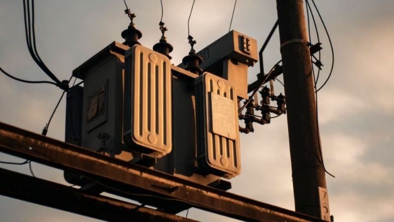
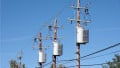
Pole-mounted unit. Image used courtesy of Pexels/Maria Amé
Pole‑Mounted Transformers
Pole‑mounted distribution transformers are mineral‑oil‑immersed units secured to utility poles and connected directly to overhead primary circuits. Modern single‑phase overhead units are commonly offered from 5 to 167 kVA, with primary voltage classes ranging from 2.4 kV to 34.5 kV. They frequently supply 120/240 V split‑phase secondaries for residential and light commercial loads.
IEEE C57.12.20 defines requirements for overhead‑type distribution transformers 500 kVA and smaller. Rural and exurban feeders frequently deploy single 25–50 kVA units for a handful of services, while three single‑phase units may be banked to serve three‑phase loads in small towns, farms, and light industry.
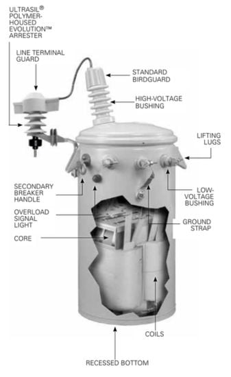
Figure 1. Single-phase overhead transformer. Image used courtesy of Eaton
Advantages
Lower installed cost for sparse loads: Existing poles and aerial rights‑of‑way eliminate civil works and underground primary duct banks, which is well-suited to long rural laterals with low service density.
Simpler set, lift, and tie‑in: Hardware is standardized, utility crews are trained to hot‑stick overhead terminations, and outages are minimized during change‑outs compared with civil excavation for underground feeders.
Limitations
Exposure to weather and impact: Overhead units face windborne debris, lightning, and icing. Enclosure integrity standards for pole‑mounted equipment (IEEE C57.12.31 and C57.12.30 for coastal environments) exist to address these conditions but cannot eliminate environmental exposure altogether.
Public‑interface concerns: Visible equipment and service drops are at odds with community design goals in denser or high‑amenity settings, a frequent driver of undergrounding decisions.
Pad‑Mounted Transformers
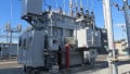
Pad‑mounted transformers (single‑ or three‑phase) sit in locked steel enclosures on concrete pads. They are the standard step‑down devices in underground residential distribution (URD), commercial campuses, and light‑industrial parks. Typical primary ratings span 2.4-46 kV with common three‑phase kVA ratings from 45 up to 10,000, depending on design and application. Secondaries often include 208Y/120 V and 480Y/277 V for commercial service.
These units localize medium‑voltage switching and protection near the load while keeping energized parts inaccessible to the public.
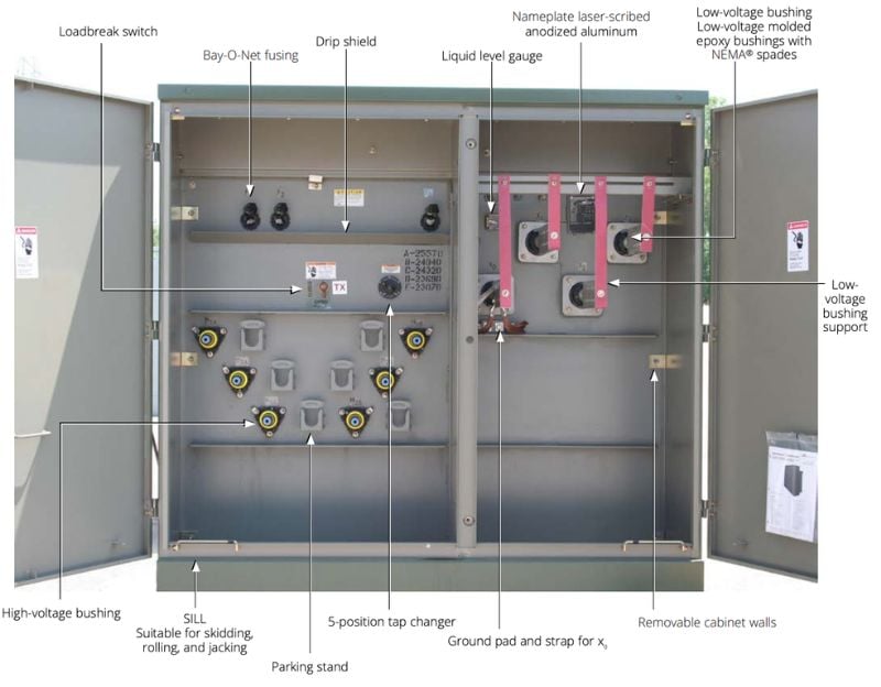
Figure 2. Three-Phase pad-mounted transformer. Image used courtesy of Eaton
Enclosure Design and Tamper Resistance
Public siting demands enclosures that resist forced entry and environmental degradation. IEEE C57.12.28 specifies pad‑mounted equipment enclosure integrity (impact, pry, pull, probe tests, lock strength, and fastener security), while C57.12.29 extends integrity for corrosive/coastal environments. Utilities routinely call up these standards in procurement documents to mitigate unauthorized access and improve field durability.
Pad‑mounted primary terminations are commonly “dead‑front,” using shielded separable elbows and junctions that meet IEEE 386 for 2.5-35 kV systems up to 600-900 A. Dead‑front apparatus keeps energized interfaces insulated and touch‑safe when the cabinet is open, a critical feature for public‑facing installations and for switching under faulted‑section isolation procedures.
Loop Vs. Radial Feed Configurations
Radial‑feed padmounts present one incoming medium‑voltage feed and serve downstream secondaries without an alternate source. They minimize first cost and cabinet complexity and are common in residential URD.
Loop‑feed padmounts include a through‑feed to form a looped primary circuit with a normally‑open point elsewhere. This topology supports back‑feeding from the opposite direction for fault isolation and service restoration. A loop‑feed transformer can also function in a radial circuit, providing flexibility for future network reconfiguration.
In both cases, cabinet layouts, bushing counts, and internal switching reflect the chosen topology; utilities typically standardize on dead‑front 200-A load-break and 600-A dead-break interfaces per IEEE 386.
Table 1. Pad vs. pole-mounted transformers comparison
| Attribute | Pole-Mounted | Pad-Mounted |
| Typical kVA ranges | 5–167 kVA single-phase; banks for 3-phase | 45–10,000 kVA three-phase families; single-phase 10–167 kVA |
| Primary voltage classes | 2.4–34.5 kV typical | 2.4–46 kV typical |
| Common secondaries | 120/240 V split-phase | 208Y/120 V, 480Y/277 V, others |
| System context | Overhead laterals, rural/exurban | URD in residential, commercial, campuses |
| Public interface | Exposed tank on pole | Locked, tamper-resistant cabinet |
| Primary terminations | Overhead bushings and cutouts | Dead-front elbows/junctions |
Selection Criteria
Load Density and Urbanization
Service density and load mix are primary drivers. Sparse rural feeders with scattered single‑family services often favor overhead pole‑mounted units due to the minimal civil work required.
As loads cluster—apartment blocks, retail centers, data rooms, electric vehicle charging depots—pad‑mounted units reduce secondary lengths, improve voltage drop, and integrate medium‑voltage switching near the load. Manufacturer specifications for pad‑mounted designs list extensive kVA selections and voltage combinations that align with medium‑to‑high density development.
Reliability Requirements
Topology matters when outage minutes have contractual or regulatory importance. Radial circuits minimize capital expense but offer no local redundancy. A cable fault or upstream device trip interrupts all downstream loads until switching is performed.
Loop systems, paired with loop‑feed padmounts, permit sectionalizing and back‑feeding from the opposite direction, supporting faster restoration and planned back‑ties during maintenance. Utilities often standardize dead‑front interfaces per IEEE 386 to enable safe, modular switching.
Maintenance Accessibility
Overhead units allow bucket‑truck access and visual inspection without excavation, but live‑line work may be required for certain operations. Pad‑mounted units centralize MV terminations at ground level in compartments designed for switching and fuse replacement with barriers and interlocks.
While no enclosure removes all hazards, enclosure integrity standards (IEEE C57.12.28/.29) and dead‑front interfaces improve maintainability in public spaces compared with open overhead construction. Local practices and worker qualifications determine energized vs de‑energized maintenance approach, and working clearances/ventilation requirements are governed by the National Electrical Code (NEC), Article 450, where applicable.
Environmental and Regulatory Considerations
Energy performance: Federal efficiency standards for distribution transformers are defined in 10 CFR Part 431. The e-CFR defines efficiency test methods and specifies minimum efficiency levels by kVA rating and transformer type, with performance evaluated at 50% load. In practice, transformer selection should account for both nameplate efficiency and expected loading to minimize lifecycle losses.
Oil containment and spill planning: Oil‑filled distribution transformers are “oil‑filled operational equipment” under the EPA’s Spill Prevention, Control, and Countermeasure (SPCC) rule (40 CFR 112). Facilities that meet storage thresholds must maintain SPCC plans and consider secondary containment or qualified alternatives for oil‑filled equipment. Site civil design sometimes incorporates curbing, gravel sumps, or vault barriers to address local jurisdictional requirements.
Public‑facing safety: Pad‑mounted siting in parks, sidewalks, and campuses demands both tamper resistance (IEEE C57.12.28) and dead‑front MV interfaces (IEEE 386). Where padmounts are near structures, NEC Article 450 provisions for ventilation, vaults, and working space apply per local adoption; the Authority Having Jurisdiction may impose setbacks or bollards for physical protection.
Environmental exposure: Coastal or corrosive atmospheres require enclosure integrity to coastal criteria (IEEE C57.12.29) for pad‑mounted equipment and corresponding pole‑mounted enclosure standards for overhead equipment, extending life and reducing maintenance.
Conclusion
Both pole‑mounted and pad‑mounted transformers perform the same essential function, but their differences matter in planning and operations. Overhead units align with modest loads over long distances, with simpler installation and lower first cost—useful in rural and exurban contexts.
Pad‑mounted units, purpose‑built for underground systems, bring enclosure integrity, dead‑front terminations, and primary switching to the curb line, supporting dense developments and public‑space siting.
Reliability expectations push many networks toward loop‑feed topologies with loop‑feed padmounts to enable sectionalizing and back‑feeding, while cost‑sensitive feeders still favor radial arrangements. Across all choices, energy-efficiency rules, enclosure integrity and connector standards, and site-specific SPCC obligations guide compliant and safe installations.