Facebook
 Google
 GitHub
 Linkedin
Designing Power Supplies for Industrial Functional Safety—Part 2: Creating a Safe Power Design
While Part 1 of this series showed what the IEC 61508 requires from power supplies to achieve functional safety, Part 2 provides insights into applying the basic functional safety standard’s principles about eliminating systematic failures and controlling random hardware failures to ensure safe power supply design.
This article is published by EEPower as part of an exclusive digital content partnership with Bodo’s Power Systems.
Check out the first part of this article series here: Designing Power Supplies for Industrial Functional Safety—Part 1: What IEC 61508 Tells Us
This Part 2 of this series details the critical distinction between systematic and random failures that can impede a safety-related system from achieving a safe state, emphasizing the necessity of a safe power supply design adhering to standards like IEC 61508. Systematic failures, which are deterministic and include both hardware and software faults, must be eliminated through proactive design modifications, such as implementing component derating, robust overvoltage protection, and proper power supply monitoring.
Conversely, random hardware failures that result from component degradation mechanisms are controlled using diagnostic measures and architectural design, primarily quantified through failure modes, effects, and diagnostics analysis (FMEDA). Effective management of both failure types—eliminating systematic weaknesses and controlling random hardware failures—is essential to meet the required safety integrity level (SIL).
IEC 61508: A Recall
Aside from knowing what the functional safety standard requires, it’s important to know the types of failures that can hinder safety-related systems from achieving the safe state when starting a safety-related system, such as safe power supply design. A safety function can either carry out positive actions to avoid hazardous situations or prevent actions from being taken to maintain a safe state. In terms of failures, a safety function can either have a systematic failure or a random one, as shown in Figure 1.
Systematic failures include both hardware and software. These failures occur deterministically due to a specific cause and can be eliminated through design modifications and other measures. For instance, IEC 61508 provides normative techniques and measures so systematic failures can be avoided and controlled. More details can be found in Part 1 of this story, which was published in Bodo’s Power Systems 8/2025.
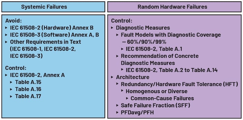
Figure 1. IEC 61508: systematic failures vs. random hardware failures. Image used courtesy of Bodo’s Power Systems [PDF]
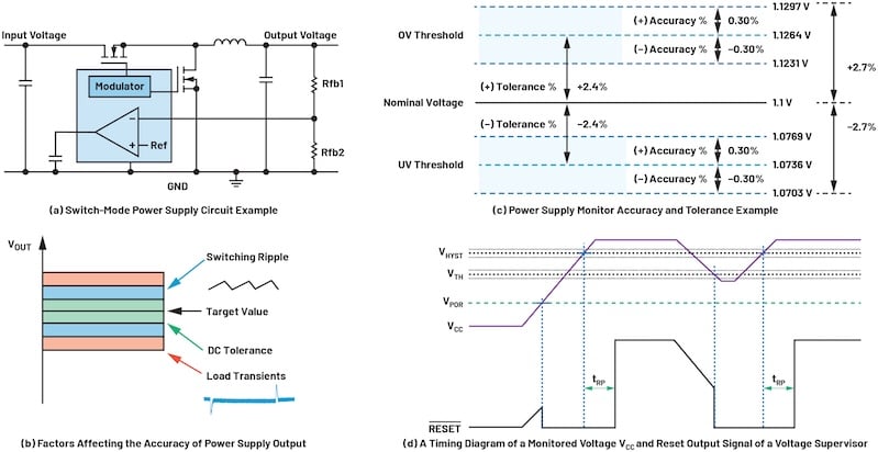
Figure 2. Power supply monitoring considerations.[1,2,3] Image used courtesy of Bodo’s Power Systems [PDF]
On the other hand, random failures can only occur in hardware. These types of failures result from one or more of the possible degradation mechanisms in the hardware happening at a random time. Thus, random hardware failures can only be controlled through diagnostic measures and the proper design of architecture.
Controlling Systematic Failures
Regardless of safety integrity level (SIL), measures against voltage breakdowns, and other power supply-related dangerous failures, are mandatory to control systematic failures. This can be in the form of passive measures such as employing passive protections (such as fuses and Zener diodes), implementing proper derating of components, and allotting sufficient operating margins.
In terms of active measures, this can be in the form of power supply diagnostic measures, such as adding overvoltage protections, windowed power supply monitoring, secondary voltage control, current limiting, and other active protection circuitries. These measures to control systematic failures are important to implement in a power supply design aiming for compliance with a certain SIL.
Aside from complying with the required performance requirements, scoping electrical, thermal, mechanical, electromagnetic compatibility, product safety, and other related standards, some questions to ponder are as follows.
Are all voltages properly monitored to enable proper power sequence? Consider different factors affecting a power supply’s output accuracy when setting the power supply monitor’s overvoltage (OV) and undervoltage (UV) thresholds to enable seamless sequencing and diagnostics. This can be seen in Figure 2.
Are sufficient protections, for example, surge protections, etc., or other measures employed to improve electromagnetic immunity? Consider protection measures such as OV/UV protection, as in the MAX6399, surge stoppers, as in the LTC4364, reverse-input protection, reverse-current, and current-limiting, as shown in Figure 3.
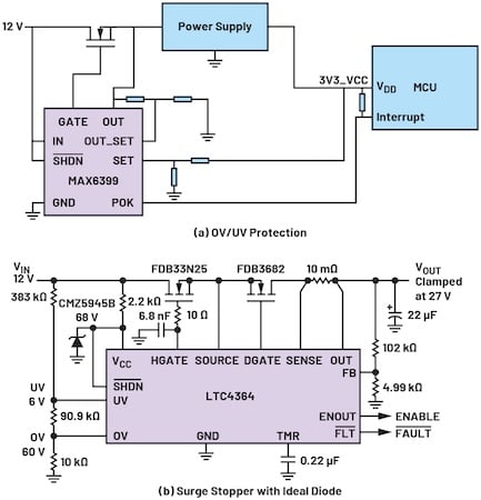
Figure 3. Employing protections to improve system reliability.[2] Image used courtesy of Bodo’s Power Systems [PDF]
Are well-tried components used according to their specifications with sufficient derating, such as 67 % of the loading condition?[4] Sufficient derating involves ensuring components operate in their safe operating area, as well as employing additional operating margins, as shown in Figure 4. For instance, a 125 °C-rated part provides sufficient derating when used to operate at 55 °C ambient operating temperature with junction temperature rising to 85 °C.[4,5,6]
Further questions of interest are: What other systematic failure modes need to be addressed? What about Back EMF (electromotive force) that can damage input circuitries[7]? Are there any timing/ pulse-width issues that can cause cross-conduction? Furthermore, it is important to check for hot spot issues that can cause thermal runaways, as shown in Figure 5.
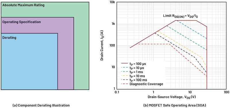
Figure 4. Employing protections to improve electromagnetic immunity.[6] Image used courtesy of Bodo’s Power Systems [PDF]
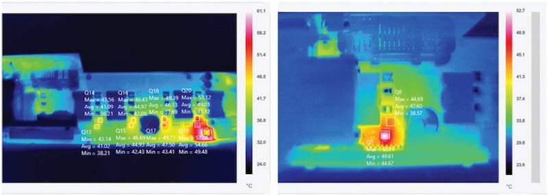
Figure 5. Hot spot comparison of a board running at full load during discharge (left) and charge (right) modes of operation, respectively.[8] Image used courtesy of Bodo’s Power Systems [PDF]
Controlling Random Hardware Failures
A failure modes, effects, and diagnostics analysis (FMEDA) document is used to analyze and quantify the impact of random hardware failures on the performance of safety-related systems. Its input includes failure rate, application, and hardware design information. Meanwhile, its output shows block failure modes and effects, failure rates λSD, λSU, λDD, and λDU, diagnostic coverage for each failure mode, and the SIL metrics. These are shown in Figure 6.
Analyzing a product with an FMEDA includes other requirements. The first requirement is to analyze the failure modes of components used to implement the safety function. The second requirement is employing additional safety (diagnostic) measures/built-in selftests (BISTs) against dangerous undetected failures to improve SIL metrics accordingly. Doing iterations until the required safe failure fraction (SFF) and probability of dangerous failure (PFH/PFDavg) metrics are met is the third requirement.
These three are complemented by other considerations; they include using functional safety compliant components,[9] which offer several benefits, or using Analog Devices’ FS-enabled parts, which provide safety application notes10 to show an IC’s failure rate information, failure mode distribution (FMD), and pin failure modes and effects analysis (FMEA) information to help speed up the system FMEDA.
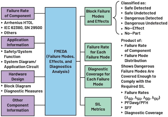
Figure 6. FMEDA composition. Image used courtesy of Bodo’s Power Systems [PDF]
Conclusion
In summary, the foundation of a robust and safe power supply design lies in a rigorous approach to failure management as prescribed by IEC 61508. Addressing systematic failures is paramount; these deterministic faults must be eliminated through proactive design choices, such as implementing windowed voltage monitoring, employing sufficient component derating, and integrating surge protection. By adopting both passive and active measures early in the development cycle, engineers can mitigate risks like thermal runaway and voltage breakdowns, ensuring the power system remains within its defined safe operating area even under stress.
Furthermore, the design must account for the unpredictable nature of random hardware failures. While these cannot be eliminated through design alone, they are effectively managed by quantifying risks via FMEDA. By meticulously analyzing failure rates and incorporating diagnostic coverage like BISTs, designers can control hardware degradation impacts to meet stringent SIL requirements. Ultimately, the synergy between eliminating systematic weaknesses and controlling random hardware failures ensures that the power supply functions not just as a power source but as a reliable backbone for functional safety systems.
References
[1] Frederik Dostal. “Determining Voltage Accuracy of Switch-Mode Power Supplies.” ElectronicDesign, October 2025.
[2] Bryan Borres and Christopher Macatangay. “Improving Industrial Functional Safety Compliance with High Performance Supervisory Circuits: Safety Critical Features—Part 3.” Analog Dialogue, Vol. 59, June 2025.
[3] Noel Tenorio and Anthony Serquiña. “High Performance Voltage Supervisors Explained—Part 1.” Analog Dialogue, Vol. 58, April 2024.
[4] IEC 61508 All Parts, Functional Safety of Electrical/Electronic/ Programmable Electronic Safety-Related Systems. International Electrotechnical Commission, 2010.
[5] Tom Meany. “De-rating: Advice from NASA & Irish Legend.” January 2019.
[6] Dan Eddleman. “MOSFET Safe Operating Area and Hot Swap Circuits.” LT Journal of Analog Innovation, April 2017.
[7] Building a Better Stepper Motor System with StallGuard and CoolStep Technologies. Analog Devices, Inc.
[8] Christian Cruz, Gary Sapia, and Marvin Neil Cabueñas. “Smart Battery Backup for Uninterrupted Energy Part 1: Electrical and Mechanical Design.” Analog Dialogue, Vol. 57, December 2023.
[9] Bryan Borres. “Improving Industrial Functional Safety Compliance with High Performance Supervisory Circuits: Using SILRated Components—Part 2.” Analog Devices, Inc., March 2025.
[10] Bryan Borres. “Know Your Safety Application Notes—Part 2: Failure Mode Distribution.” Analog Dialogue, Vol. 59, October 2025.
This article originally appeared in Bodo’s Power Systems [PDF] magazine.