Facebook
 Google
 GitHub
 Linkedin
Advanced Partial Discharge Testing for Modern Power Modules
Modern power modules need PD testing that goes beyond traditional standards. This article looks at advanced diagnostic methods that help improve how we assess insulation reliability.
Earlier, we looked at some practical limits of using standard IEC partial discharge (PD) testing for modern power modules. While these limits exist, IEC PD testing is still a widely used reference for insulation screening and qualification. But as fast-switching technologies become more common in power modules, engineers are adding new diagnostic methods that better reflect real operating conditions.
These methods can include PD testing timed with switching events, fast transient voltage checks, time-frequency signal analysis, and testing at higher temperatures.
Figure 1. Laboratory measurement equipment used to capture high-frequency electrical signals during diagnostic testing of power electronic systems. Image used courtesy of Pixabay.
Fast-Rise-Time Partial Discharge Testing
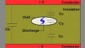
Rapid switching in modern converter designs leads to high dv/dt levels, which cause sharp changes in the electric field across insulation layers inside power modules. The equation shows that these changes also depend on the insulation thickness (d). For example, an 800 V voltage change in 50 ns gives an estimated dv/dt of 16 kV/µs.
$$E(t) = \frac{V(t)}{d}$$
If the insulation thickness is 0.4 mm, the electric field can change at nearly 40 MV/m per microsecond. These sudden changes create concentrated electrical stress, especially at material interfaces, structural irregularities, and sharp metal edges inside the module. These transient field conditions are much closer to real converter operation than the slower sinusoidal voltage ramp often used in partial discharge testing.
Fast-rise-time testing uses an impulse, step-like voltage waveform with a rise time from a few nanoseconds to hundreds of nanoseconds. These waveforms are created in the lab with an impulse generator that produces high-voltage transitions.
Because PD signals from fast transient stress have high-frequency components, the measurement system needs enough bandwidth to capture them accurately. With wide bandwidth PD sensors and fast coupling networks, discharge activity can be seen right after a voltage edge, when transient electric stress is usually highest.
Switching-Synchronized PD Measurement
In power modules, PD events do not happen evenly throughout the voltage cycles. Instead, they often cluster around certain switching moments. Fast voltage changes from pulse-width modulation (PWM) during converter operation cause brief disturbances in the electric field within the insulation. These changes can temporarily increase local electrical stress, especially at material interfaces or areas with different shapes.
Switching-synchronized PD measurement records discharge events along with a timing reference from the converter, usually using the PWM control signal and the gate driver signal. This setup lets the PD detection system capture discharge pulses and log the switching signal that triggers the voltage change.
By matching PD and switching signals on the same scale, we can identify the discharge event that happens right after the switching event. High-speed data acquisition systems allow analysis with microsecond and nanosecond precision, helping to separate PD pulses linked to switching edges from other electrical disturbances in the system.
Synchronizing PD detection with converter switching also offers diagnostic benefits. It makes it easier to tell true partial discharge pulses apart from switching noise, which often looks like PD in standard measurements. This method helps find insulation regions that are more likely to face repeated transient stress, giving useful insights when checking reliability in high-speed power modules.
Ultra-High-Frequency (UHF) PD Detection
When PD occurs, it generates very fast current pulses that create broadband electromagnetic emissions. These emissions reach into the ultra-high-frequency spectrum, so PD activity can be detected using methods beyond traditional coupling approaches.
UHF PD detection systems use sensors that work in the hundreds of megahertz to gigahertz range to capture these signals. Since PD has high-frequency components, monitoring the spectrum gives another way to observe discharge activity, even in noisy electrical environments.
The UHF method offers several advantages for PD detection in power modules, where switching activity and EMI are common. One key benefit is that the higher frequency lets UHF sensors detect PD signals that are less affected by lower-frequency switching disturbances.
Because UHF relies on radiated electromagnetic signals, it allows for PD detection without needing an electrical measurement circuit. Another advantage is better defect localization, since multiple sensors can be used and signal amplitude comparisons can help estimate where the PD originates.
| Parameter | Conventional PD | UHF PD |
| Bandwidth | kHz-MHz | MHz-GHz |
| Noise immunity | Moderate | Higher |
| Localization capability | Limited | Improved |
Table 1. Comparison of bandwidth, noise immunity, and localization capability between conventional PD discharge detection and UHF sensing methods used in power modules.
When adding UHF detection to power module testing, sensor placement is very important. Sensors are often placed near areas where electromagnetic emissions from PD events can be captured effectively, such as close to the module housing or insulation boundaries. Proper shielding and calibration are also essential to ensure accuracy in PD measurement and to distinguish PD signals from other high-frequency disturbances in the power module.
Time-Frequency Domain PD Signal Analysis
Relying only on pulse magnitude in traditional PD measurement can be misleading, since it does not always show the true severity or root cause of the discharge. Two discharge events with similar amplitudes may have different energy levels and come from different defect mechanisms. For this reason, it is important to evaluate PD using both time and frequency domains to estimate the energy associated with a discharge pulse from the instantaneous voltage and current during the event.
$$E_{PD} = \int v(t)i(t)dt$$
Different insulation defects produce different spectral characteristics, so analyzing the frequency distribution of discharge signals can help identify the type of defect responsible, as shown in Table 2 below. Discharge sources are classified based on spectral differences that result from variations in discharge geometry, propagation paths, and the electrical properties around the internal insulation material.
| Defect Type | Frequency Range | Behavior |
| Internal Void | 50-300 MHz | Repetitive pulses |
| Surface discharge | 300-800 MHz | Bursty activity |
| Interface discharge | Broadband | Irregular patterns |
Table 2. Typical frequency characteristics of PD signals associated with different insulation defect types, illustrating how spectral analysis can assist in identifying discharge sources.
PD Testing in Elevated Temperatures
Temperature greatly affects how insulation materials behave electrically in power modules. As temperatures rise, key material characteristics change, which affects electric field distribution across the insulation and alters the conditions for PD to occur. A common effect is the reduction of partial discharge inception voltage (PDIV) as temperature increases.
This behavior is often described using an empirical relationship shown below. Here, PDIVT0 is the inception voltage at a reference temperature T0, and (α) is the material-dependent temperature coefficient. As temperature rises, the decrease in PDIV means that discharge activity may start at lower voltages than those seen at room temperature.
$$PDIV(T) = PDIV_{T0}(1 - \alpha(T - T_0))$$
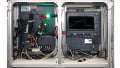
For the test setup, elevated temperature PD testing is usually done by placing the test specimen inside a temperature-controlled chamber while applying the required high-voltage stress. The chamber allows the module or insulation sample to reach stable thermal conditions before measurements are taken.
Accurate testing requires temperature stabilization, since transient thermal gradients can distort electric field patterns and affect measurement repeatability. Once the desired temperature is reached, PD measurements are taken using standard detection methods while keeping environmental conditions controlled.
Integrating Advanced PD Methods in Module Qualification
Today’s insulation assessment favors a multi-method approach instead of relying on a single test. Each technique offers a unique perspective on how insulation performs under different electrical and thermal stresses, giving power engineers a more complete picture of system behavior.
A layered diagnostic strategy usually starts with baseline PD measurement to confirm basic insulation integrity, then adds advanced methods to assess electrical performance under dynamic stress, temperature changes, and aging. This helps engineers better understand insulation behavior and likely failure modes in power modules.