Facebook
 Google
 GitHub
 Linkedin
Combining Waveforms in a Power System to Cancel Harmonic Components
Harmonics can cause transformers to fail, motors to burn out, circuit breakers to trip (nuisance tripping), and neutral conductors and other parts of a power distribution system to overheat. Severe overheating leads to electrical fires.
Harmonics are caused by nonlinear loads that draw current in pulses, resulting in a distorted waveform. Harmonics is a source of power quality problems that lead to overheating of circuit components. Harmonics mitigating transformers are used to reduce harmonics in power distribution systems.
When harmonics are present, distorted voltage and current waveforms are present on the lines. The distorted waveforms must be analyzed to determine the type and quantity of harmonics that are present. When harmonics are present, the higher-order harmonics add together with the fundamental to produce the resultant waveform. The resultant waveform is the waveform measured by a power quality analyzer and can include different harmonics. Fourier analysis is used to analyze the waveforms. There are many types of Fourier analysis, but the simplest concept is the Fourier transform.
The Fourier Transform
The resultant waveform must be analyzed with the Fourier transform to learn about the harmonics present. The Fourier transform is the mathematical method of converting a time-based waveform, like a sine waveform, into frequency-based information. This is equivalent to breaking down (decomposing) a periodic waveform into a series of sine waveforms that can be added together to reproduce the original waveform (see Figure 1). The Fourier transform is used to find the frequency and magnitude of the harmonics present on the lines. The output of a power quality analyzer gives the relative magnitude of each harmonic.
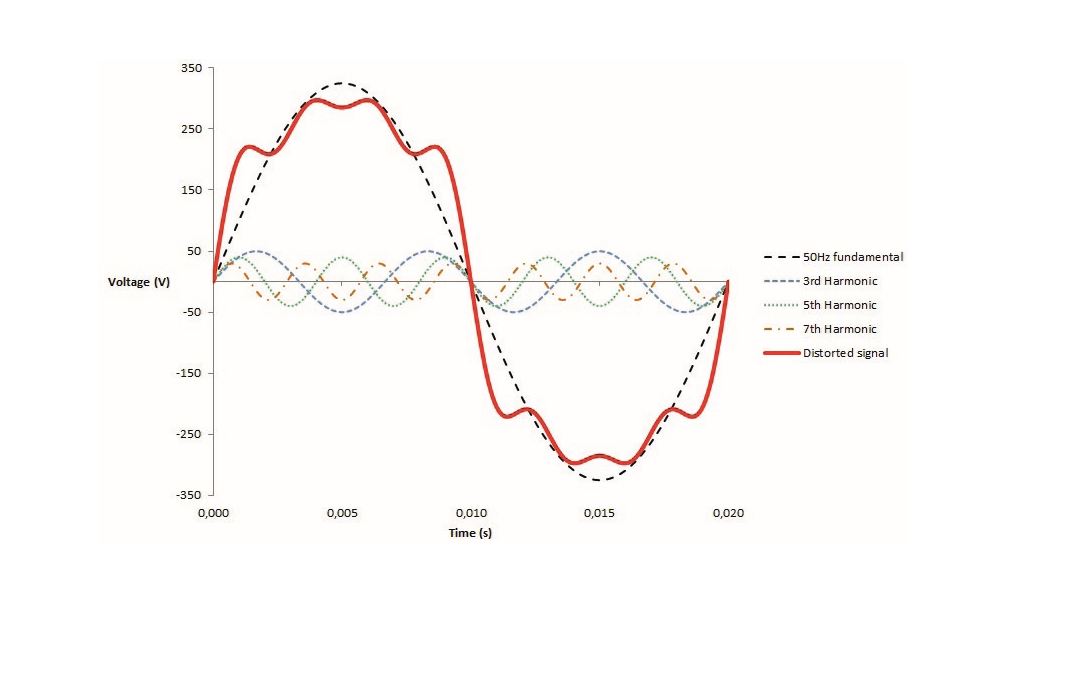
Figure 1. Fourier analysis is used to decompose a distorted wave into its component harmonics. Image courtesy of SALICRU
Combining Waveforms
The waveforms from different loads combine on the lines at any point where two or more wires come together in a junction. This typically happens at the connection points of the windings within a transformer or at a common bus feeding two or more transformers.
When sine waveforms combine, they add together, and the resultant waveform has a value equal to the sum of the individual values. If one of the waveforms is positive and the other is negative, and both are at the same numerical value, they are said to cancel. If two current waveforms are exactly out of phase with each other, with one equal to +10 A and the other equal to –10 A, the resulting current at that instant has a value of 0.
Note
Jean Baptiste Joseph Fourier developed the idea behind Fourier analysis. Fourier analysis takes a time-varying signal, such as a source with harmonics, and transforms it into the frequency components that make up the signal.
If two current waveforms are out of phase with each other and they do not exactly cancel, the resultant waveform will have a non-zero value. When an SMPS draws current in pulses, the pulses are separated from each other. If one of these waveforms is shifted 60° relative to the other and the waveforms are added, the resultant has two peaks for every peak of the original waveform (see Figure 2). This is the type of waveform shift and recombination that happens in transformers with a standard delta-wye winding or a wye-zigzag winding. The combined waveform is found on the line side of either a standard delta-wye or wye-zigzag transformer that feeds single-phase, line-to-neutral, nonlinear loads. This results in the cancellation of the triplen harmonics.
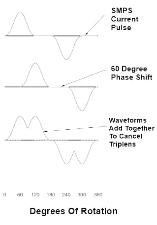
Figure 2. Waveforms add together when combined at a wiring junction. A 60° phase shift cancels triplen harmonics.
The combination waveform created by a delta-wye or a wye-zigzag transformer can be combined with two other waveforms with appropriate phase shifts to create a new waveform (see Figure 3). This waveform is a result of canceling the 5th, 7th, 17th, and 19th harmonics in addition to the triplen harmonics that were canceled by the initial phase shift. This additional phase shift can be accomplished with delta-zigzag transformers in parallel with wye-zigzag or delta-wye transformers. The combined waveform will be seen at the power busbar upstream of the transformer pair.
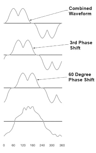
Figure 3. Further waveform shifts are used to cancel higher-order harmonics.
If the load on a transformer changes, the waveforms get out of balance and do not cancel. Additional combinations of phase shifts could be designed to eliminate more harmonics, but the benefits would be very small. The transformer bank would have to be modified every time the load changes. This can happen whenever a computer is turned on or off, or the load on a variable-speed motor drive changes. It is not practical for this type of transformer bank to be modified with every load change.