 Facebook
 Google
 GitHub
 Linkedin
Transformer Power Factor and Impedance
This article gives an overview of transformer impedance and short circuit stress.
In accordance with Lenz's law, a transformer induces a counter-voltage that opposes the source voltage. When there is no load on the secondary, the exciting current creates a small magnetic field that induces a potential in the secondary. When there is no load to consume power, the circuit is almost purely reactive. This means the counter-voltage is at its maximum, the power factor is low, and the current in the primary and secondary are 180° out of phase.
Note
With no-load, a small amount of current is drawn from the primary side to set up the required magnetic flux in the magnetic core. This is known as the “no-load current.”
The no-load current is approximately 3-5% of the full load current and accounts for the losses in the transformer.
Since the current in the secondary is 180° out of phase with the current in the primary, the magnetic field in the secondary is also 180° out of phase with the magnetic field in the primary. Magnetic lines of flux of opposite polarities that occupy the same space cancel each other. As the lines cancel one another, the ability to store energy in the magnetic field (inductance) is reduced. The reduced field size means that the inductance is lowered, and therefore the inductive reactance is lowered. As the reactance is lowered, the relative importance of resistive load elements increases. The phase angle between the current in the two coils decreases, and the power factor increases.
Power factor (PF) is the ratio of true power used in an AC circuit to apparent power delivered to the circuit. Power factor is expressed as a percentage. True power equals apparent power when the power factor is 100%. When the power factor is less than 100%, the circuit is less efficient and has a higher operating cost. To calculate the power factor, apply the formula:
$$PF=\frac{{{P}_{T}}}{{{P}_{A}}}\times 100$$
where PF = power factor (percentage)
PT = true power (in W)
PA = apparent power (in VA)
100 = constant (to convert decimal to percent)
In other words, a transformer operating under no-load conditions has a low power factor because the circuit is almost purely reactive. As the load on a transformer increases, the reactance decreases, and the power factor increases. At full load, the power factor approaches 1. Loads with a low power factor draw considerably more current than loads with a power factor near unity.
Transformer Impedance
The induced counter-voltage in a transformer is 180° out of phase with the source. The difference between this counter-voltage and the source is the voltage dropped across the coil to provide flux to excite the coil. If the circuit were purely resistive without the inductive reactance, the low nominal resistance would allow a very high current to flow, which could destroy the coil. Therefore, the transformer coil impedance is very important to transformer operation.
A single-phase transformer is designed with enough turns in the coils to provide the proper voltage at the output. The user does not need to be concerned with the design as long as the operation is within the design parameters. When a voltage is induced in the secondary, the transformer provides the rated voltage and current. As the load increases from zero to full load, the voltage drop increases.
In a 3-phase transformer bank, composed of three individual single-phase units, the impedance is very important. At no load, the output voltage is equal to the rating of the coils. As a load is placed on the system, the situation changes. All three transformers in the bank should have the same impedance to ensure that the voltage drop across each coil is the same (see Figure 1). If the three transformers in the bank have different impedances, the voltage drop across the coil with the highest impedance is higher than the voltage drop across the other coils. When the transformers have unequal impedances, the voltage available from the transformer is different for each phase as the load increases from zero to full load.

Figure 1. Transformer banks must have an equal impedance to deliver equal voltage. Image Courtesy of AllAboutCircuits
It is common for delta systems to use two transformers of one kVA rating and the third transformer with a higher rating (see Figure 2). This is used on the 120/240 3-phase 4-wire systems with a high leg to the ground. The large transformer is used for the single-phase loads while also providing power for the 3-phase loads. The kVA ratings are not equal, but the impedance of each is as close as possible.
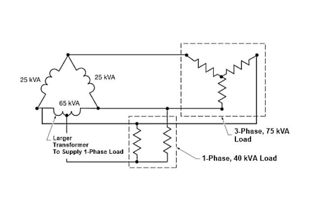
Figure 2. Single-phase loads on a delta system add extra load. One transformer must be larger to balance the load
Short Circuit Stress
An energized coil on a transformer creates an electromagnet. When a current flows through a conductor that has been wound into a coil, the various turns attract each other at all points because the current is flowing in the same direction in all turns. Two electromagnets reside in a transformer since it usually consists of a primary and secondary coil wound over one another. The currents in these two windings are opposite in direction, and there is a force of repulsion between the coils at all times. Under normal circumstances, these forces are small. However, these forces are multiplied many times during a short circuit.
There is a tendency for the windings to deform in response to the stress applied by the electromagnets during a short circuit. This can cause the coils to move, or telescope, in opposite directions. Once the movement of the coils starts, the transformer is often damaged or destroyed. To minimize the probability of telescoping, the primary and secondary windings are electrically centered with respect to each other on the core leg. This means that the coils are designed so that the electrical center of the two coils is in an identical position. The core and coil assembly of a 3-phase core-type transformer has the coils supported at both ends by support blocks with resilient pads. The support blocks are mounted on the frame, which supports the entire core and coil assembly. The core and coil assembly of a single-phase shell-type transformer has a permanently welded core clamp that cradles the core and minimizes the stress.
Telescoping problems become even more complex when transformers are specified with taps. Taps may appear on either or both of the windings. Most commonly, taps are built into the primary or high-voltage winding. The electrical center of one of the windings is moved away from the companion winding's center when the customer connects to a tap point other than the standard ratio. This increases the probability of telescoping under fault conditions.
Related Content


Very informative. Thank you