Facebook
 Google
 GitHub
 Linkedin
Practical Limitations of IEC Partial Discharge Standards in Power Modules
IEC partial standards miss dv/dt, thermal, and micro-PD effects in power modules, limiting their value for inverter-driven reliability prediction.
Today’s power semiconductor modules face tougher conditions and more thermal stress because they run at higher voltages and switch faster. Partial discharge (PD) testing is still a main qualification method, but it was originally meant for traditional bulk insulation, not the compact and fast-switching setups found in modern modules. Because of this, it is unclear if IEC PD testing can accurately predict how long inverter systems will last.
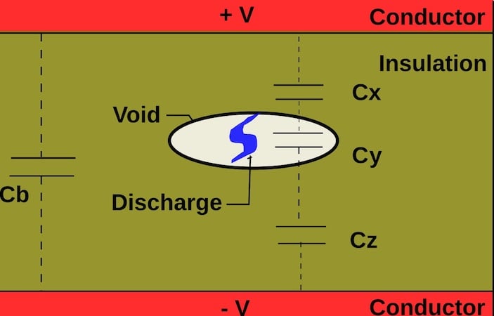
Figure 1. Conceptual illustration of partial discharge within an insulated system. Image used courtesy of Wikimedia.
Understanding Partial Discharge in Power Modules
Partial discharge is a major reliability challenge for power modules and can be hard to understand. In traditional insulation systems, PD usually means failure is near, but in power modules, PD is more of a gradual deterioration process. The damage builds up in certain areas and is mostly affected by modern packaging materials and design, not just insulation thickness.
Switching from traditional bulk insulation to modern embedded insulation has changed high-voltage system design. Older equipment used large, uniform insulation volumes of oil, air, or solid materials. In contrast, power modules use compact, layered insulation. They rely on materials like silicon gel for electrical insulation and stress relief, epoxy molding compounds for strength and protection, and ceramic metal DBC interfaces for both insulation and heat management. In these systems, insulation gaps are often only a few millimeters wide and have uneven electric fields because of sharp metal edges, material joins, and bond wires.
Partial discharge usually happens in tiny voids, at the edges where materials meet, or at triple points, not in large cavities. The energy from each event is often too small for standard measurement systems to detect, and the charge measured from outside may not show the real damage happening inside. So, in these systems, PD is not seen as big, obvious discharges but as repeated small discharges in high-stress spots that are hard to see directly.
Failure Modes Driven by Low Energy PD
As mentioned earlier, PD does not cause sudden failure but instead gradually affects the power module. Unlike bulk insulation systems, power module insulation fails slowly due to chemical degradation, carbon tracking, and material erosion. Low-energy PD creates reactive species like ozone and free radicals, which break down polymer chains and reduce elasticity, dielectric strength, and adhesion over time. Repeated discharges can also carbonize silicon gels or epoxy surfaces, creating conductive paths that focus local electric fields and speed up aging.
Intent of IEC Partial Discharge Standards
The IEC 60270 testing standard for partial discharge was developed to provide a uniform and comparable method for detecting and measuring PD in high-voltage insulation systems. The standard's primary objective is to ensure consistent measurements under controlled electrical conditions, rather than to predict specific failure mechanisms. This distinction is critical when applying IEC 60270 results to power modules.
The standard assumes significant dielectric volumes, where discharge phenomena occur within relatively large insulating materials, such as air-filled voids in switchgear assemblies or oil-immersed transformer insulation. In these applications, PD events generate sufficient energy for external detection, and the magnitude of discharges correlates closely with the progression of insulation deterioration.
For quasi-uniform electric fields, the IEC 60270 testing method assumes that the electric field distribution within the insulation is relatively uniform, without significant geometric field enhancement. This allows apparent charge measurements to serve as valid indicators of internal discharge intensity. The standard's protocols are based on the application of sinusoidal voltage at power frequencies (50 or 60 Hz), resulting in gradually varying electric fields and consistent phase-resolved PD patterns. The approach presumes that discharge characteristics are primarily influenced by voltage magnitude, rather than by rapid transient events, thereby ensuring repeatability.
Sinusoidal Testing vs PWM Reality
A significant limitation of IEC PD testing for power modules is related to the voltage waveform employed. PD behavior is influenced not only by peak voltage but also by the rate of electric field rise (dv/dt), internal field distribution, and repetition frequency. These parameters differ substantially between the controlled IEC test environment and actual inverter operation
Under IEC 60270, PD measurements are typically conducted using slowly varying voltage stress, most commonly with 50 or 60 Hz sinusoidal AC excitation. This approach results in a gradual buildup of the electric field over milliseconds, and if PD occurs, it typically appears near the voltage peak with stable characteristics. Because the voltage waveform is sinusoidal, the associated dv/dt remains inherently low, even at elevated test voltages.
$$\frac{dV}{dt} = V_{peak} \cdot \omega \cdot \cos (\omega t) $$
Smooth DC ramps are also used, particularly to assess partial discharge inception voltage (PDIV), in which the applied stress increases quasi-statically to minimize transient effects.
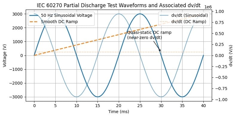
Figure 2. IEC 60270 partial discharge test waveforms and associated dv/dt. Image used courtesy of Bob Odhiambo.
Inverter-Driven Electric Stress in Power Modules
In practical inverter applications, power modules are subjected to stress conditions that differ fundamentally from those assumed in standard PD testing. Rather than experiencing slowly varying fields, modern IGBT and SiC-based converters generate rapid voltage transitions with rise rates between 10 and 100 kV per microsecond.
The rapid increase in electric field can initiate partial discharge even when the peak voltage remains below the PD inception threshold observed during sinusoidal testing. In these cases, discharge initiation is primarily governed by dv/dt-related mechanisms, including rapid charge injection, capacitive current displacement, and transient field enhancement at material interfaces, rather than by steady-state dielectric strength alone.
Inverter operation may also induce voltage overshoot and ringing as a result of parasitic inductances and capacitances within the module package, DC-link, and gate driver circuits. These transient phenomena can temporarily elevate the nominal DC-link voltage, exposing internal insulation to stresses that surpass those encountered during IEC AC qualification. Consequently, a module that exhibits no partial discharge under sinusoidal testing may still experience PD during switching events.
Additionally, PWM excitation imposes asymmetric and repetitive voltage stress patterns that differ significantly from sinusoidal waveforms. The highly repetitive and unipolar characteristics of inverter waveforms result in uneven electric field distribution and localized space charge accumulation at insulation interfaces. Over time, this increases the likelihood of PD in regions that remain inactive during AC testing, further diminishing the correlation between IEC partial discharge results and actual inverter-driven reliability.
Sensitivity Limits for Micro-Scale Partial Discharges
A less obvious challenge of using IEC partial discharge measurement for power modules is the sensitivity limit of apparent charge-based detection. IEC 60270 is designed to detect enough energy during PD events in large insulation systems, making it easy to separate from background noise. But in compact power modules, discharges happen on a much smaller scale, both physically and energetically, which makes them harder to detect.
IEC measurements determine PD by measuring apparent charge from current pulses in the test circuit. In real test setups, the smallest charge that can be detected depends on things like the sensitivity of the coupling capacitor, measurement impedance, data acquisition system, and the need to reduce outside electromagnetic interference. To keep measurements stable, noise filtering and bandwidth limits are used, which set a lower limit for what can be detected. While this works for bulk insulation systems, it makes it harder to detect small, short discharges that often happen in the embedded insulation of power modules.
Cumulative PD Aging vs Pass/Fail Thinking
The main difference between IEC PD testing standards and real power module reliability is in how acceptance is defined. IEC qualifications mostly use an event-driven pass/fail model, where a PD test at a set voltage decides if a module passes, based on whether the measured apparent charge stays below a set limit. This approach treats PD as an unusual or isolated event and focuses more on the strength of each discharge than on how often it happens.
In power modules, PD damage follows a clear pattern. Over their lifetime, these modules go through billions of voltage switching cycles under inverter conditions, and even small discharge events, well below traditional thresholds, can cause significant damage if they happen often.
Here, how often PD occurs is the main factor in aging, slowly wearing down polymer insulation and changing local electric fields without producing large, easy-to-detect discharges. This means insulation can age a lot without reaching catastrophic discharge levels during standard tests, showing a key limitation of the pass/fail PD standard for inverter-operated power modules.
What IEC PD Standard Can Still Do for Power Module
Even with its limitations, the IEC PD standard still provides real value when used as intended. IEC PD testing is good at finding major insulation problems like large voids, delamination, or manufacturing mistakes that could threaten reliability. In manufacturing, PD measurements are a useful quality control tool, and the standards work well for checking high-voltage modules as they arrive. They give a consistent way to judge insulation quality and compare different module designs under controlled conditions.
However, IEC PD testing should not be seen as a final measure of inverter-driven reliability or long-term insulation performance. To truly assess insulation strength in real conditions, engineers need to go beyond the traditional IEC pass/fail approach and use new PD testing methods that account for fast dv/dt stress, cumulative aging, and transient overvoltages. Using these modern methods together can help bridge the gap between lab tests and real-world power module reliability.