Facebook
 Google
 GitHub
 Linkedin
Pulsed Inductance Measurement Replaces Reactance Method for Large Power Chokes
In this article, learn why pulse measurement has advantages over the conventional reactance-based method when it comes to determining the inductance of power chokes.
Article co-authored by Robert Rohn, Research and Development at Hans von Mangoldt.
This article is published by EEPower as part of an exclusive digital content partnership with Bodo’s Power Systems.
For historical reasons, the inductance of chokes with sheet metal cores is still often determined by measuring their reactance during production. In this method, the choke is subjected to line current and line voltage, and the reactance is calculated based on the RMS values of current and voltage. From this, the inductance is derived. However, this approach has several significant disadvantages compared to the pulse measurement method. Therefore, Hans von Mangoldt GmbH is in the process of switching its inductance measurement in production to pulse measurement using the Power Choke Tester DPG10 series.
This article outlines both the pulse measurement principle and the conventional reactance-based method, highlighting the advantages of pulse measurement.
In addition, the practical application of the Power Choke Tester DPG10 series at Hans von Mangoldt GmbH in the series production of wound products with sheet metal cores, covering a power range from 1 kVA to over 1 MVA, is presented.
Finally, it will be shown how the Power Choke Tester DPG10 series can be integrated into fully automated production lines for mass-produced winding goods using the new InterfaceBox INT1, without having to write your own software.
From the curves of the current i(t) and the voltage v(t) on the test specimen, the following variables can be calculated with a single pulse:
- Differential inductance Ldiff(i) (Figure 2) and Ldiff(∫Udt)
- Amplitude inductance Lamp(i) and Lamp(∫Udt) (also called secant inductance)
- Flux linkage ψ(i)
- Magnetic co-energy Wco(i)
- Flux density B(i), if the core cross-section and number of turns are specified
The DC resistance is measured separately. The Power Choke Tester DPG10 Series is also suitable for 3-phase chokes with the optional 3-Phase Extension Unit.
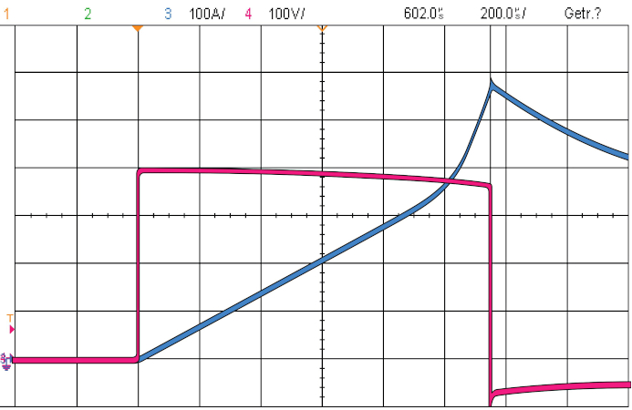
Figure 1. Current and voltage curve of the measuring pulse.
CH1: Current 100A/div
CH2: Voltage 100V/div
Image used courtesy of Bodo’s Power Systems [PDF]
Pulse Measuring Principle of the Power Choke Tester DPG10 Series
With this measuring principle, a square-wave voltage pulse is applied to the test specimen, as in most real power electronics applications. This results in a ramp-shaped current increase in the test object (Figure 1), whose slew rate di/dt is dependent on the current-dependent inductance L(i). The measuring pulse is cut off again when a preset maximum current or a preset pulse duration is reached.
From the curves of the current i(t) and the voltage v(t) on the test specimen, the following variables can be calculated with a single pulse:
- Differential inductance Ldiff(i) (Figure 2) and Ldiff(∫Udt)
- Amplitude inductance Lamp(i) and Lamp(∫Udt) (also called secant inductance)
- Flux linkage ψ(i)
- Magnetic co-energy Wco(i)
- Flux density B(i), if the core cross-section and number of turns are specified
The DC resistance is measured separately. The Power Choke Tester DPG10 Series is also suitable for 3-phase chokes with the optional 3-Phase Extension Unit.
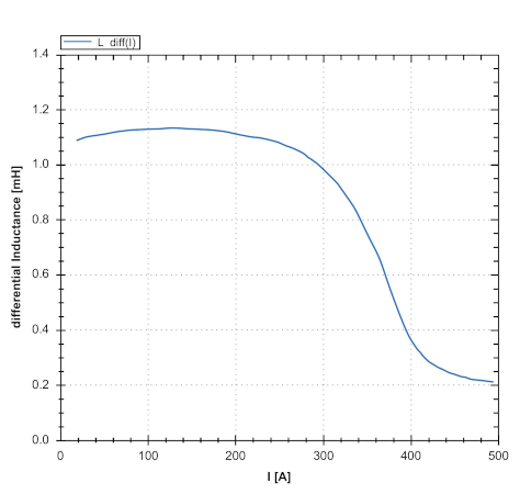
Figure 2. Diagram of the differential inductance Ldiff(i) of a filter reactor. Image used courtesy of Bodo’s Power Systems [PDF]
Advantages of the Power Choke Tester DPG10 Series at a Glance
- Extremely wide range of applications that cannot be achieved with any other commercially available inductance meter; suitable for almost all types of inductive power components from small SMD chokes to power chokes in the MVA range weighing several tonnes.
- Very wide current range, currently available from < 0.1 A to 10000 A
- Suitable for all core materials from < 5 Hz to many hundreds of kHz
- Very simple operation, test results within seconds
- Small and lightweight, even the 10 kA model can be used mobile on a trolley
- Affordable price point despite the very high measurement currents
- Pulse energy currently available up to 15 kJ
- No thermal influence on the DUT
- Also suitable for 3-phase chokes by means of the 3-Phase Extension Unit
Conventional Measurement of Reactance with Mains Voltage and Mains Current
When measuring the reactance, the rated current and rated voltage (50 Hz or 60 Hz) are usually applied to the test specimen. Electromechanical variable transformers or regulated inverters with sine filters are used for this purpose. The RMS values of the current and voltage are measured. According to general AC theory and neglecting the ohmic resistance, the inductance is then calculated as
\[L=\frac{V_{rms}}{2\pi f* I_{rms}}\,\,\,\,\,\,\,\,\,\,(1)\]
Taking the ohmic resistance into account the equation results in
\[L\frac{\Bigg(\sqrt{(\frac{V_{rms}}{I_{rms}})^{2}-R^{2}}{}\Bigg)}{2\pi F}\,\,\,\,\,\,\,\,\,\,(2)\]
The fundamental problem with this is that no sinusoidal voltages and currents are present due to the extremely non-linear behaviour of the core material. This applies especially to iron core materials, which usually have a very much lower permeability at the origin of the B-H curve than in the normal operating range, which then decreases again as the saturation increases.
When a sinusoidal current is applied to the test specimen, the resulting voltage deviates from a pure sinusoidal waveform. Conversely, applying a sinusoidal voltage leads to a current response that is non-sinusoidal.
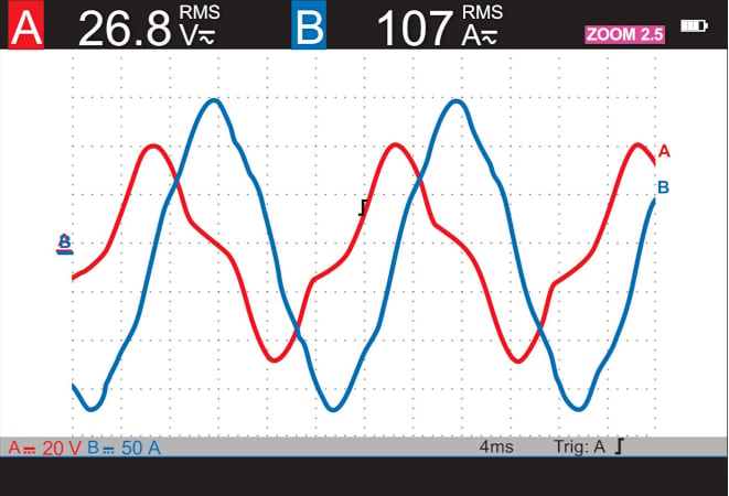
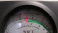
Figure 3. Current and voltage shape for a measurement with 50Hz mains voltage.
CH1: Voltage 20V/div
CH3: Current 5A/div
Image used courtesy of Bodo’s Power Systems [PDF]
In practice, neither sinusoidal currents nor sinusoidal voltages are typically observed with this measurement method unless the supply is provided by an electronically controlled inverter. The measured signals exhibit significant harmonic distortion. The typically smooth crests of the sinusoidal current become pointed, and in extreme cases even needle shaped (Figure 3).
With such distorted curves, a RMS value measurement of voltage and current and the subsequent calculation of the inductance according to equation (1) or (2) are incorrect for two reasons:
- The equations are derived from the general AC theory. However, this is only valid for sinusoidal variables and linear relationships.
- For the RMS value measurement, the measured variable is by definition quadratically evaluated and integrated over one period. This is based on the heating effect of alternating current in a resistive load. The RMS value of an alternating current is equivalent to the heating effect of a corresponding direct current. This has nothing to do with magnetism! Due to the high crest factor, this method systematically yields values for current and voltage that are significantly higher than those of the fundamental waveform.
In principle, therefore, this measurement method is of little use in the non-linear range. Due to a lack of better alternatives, this measurement method was justified in the past, at least up to the saturation limit of the core material. With the advent of the pulse measurement method, however, a measurement method is now available that is more precise, faster, simpler and, starting from certain power ratings, also more cost-effective.
When comparing the measurement results, the conventional reactance measurement most closely corresponds to the amplitude inductance Lamp(i) determined with the pulse measurement method (up to the saturation limit). However, the additionally available curve of the differential inductance Ldiff(i) can provide valuable insights into the characteristics of the components and the magnetic circuit.
Comparison Power Choke Tester DPG10 Measurement ↔ Conventional Reactance Measurement at a Glance
| DPG10 Series Pulse Measurement | Reactance Measurement | |
| Applicability | Delivers correct results even in the non-linear range. | Only allowed in the linear range, incorrect measurement results in the non-linear, saturated range. |
| Duration of a Measurement | A complete measurement curve takes only a few seconds, since only a single measuring pulse is necessary for a single-phase measurement. | Creating a complete measurement curve takes a long time because many measurement points have to be measured individually. |
| Mobility | Even the largest models of the DPG10/20 series are mobile, so that the measuring station can be easily brought to the test object. | For larger currents and power levels, a large, heavy, stationary power supply via a variable transformer or a converter with a sine-wave filter is required. Therefore, the test object must be brought to the stationary test station, even if it is very large. |
Practical use of the Power Choke Tester DPG10 series at Hans von Mangoldt GmbH
Founded in 1941, Hans von Mangoldt GmbH has consistently stood for excellence in quality and innovation in the manufacturing of inductive components. With more than eight decades of experience, it remains a reliable partner, especially where customized solutions are required.
The product portfolio encompasses a broad range of inductive components used in various applications: from industrial power supplies and grid systems to power electronics, as well as demanding environments such as maritime and desert conditions. The challenge lies not only in manufacturing, but especially in the individual design of the components - always tailored to the specific requirements of each customer. Just as important as the technical expertise is the reliability of the products. Customers depend on on-time delivery and consistently high quality.
To ensure consistent quality, Hans von Mangoldt GmbH relies on the Power Choke Tester DPG10 from ed-k and is currently in the final stages to replace the old testing transformers and power meters, which were not only complex to use, but also not mobile and required high maintenance effort due to their moving components. With the DPG10, this is no longer relevant. The compact design allows flexible use in the production line - without elaborate modifications or long set-up times.
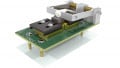
Figure 4 showcases the comparison between the old transformer-based test bench and the new DPG10-4000B/F /F with an optional 3-Phase Extension Unit. The conventional test system consists of a variable transformer with 100 A and another fixed ratio transformer to increase testing capabilities up to 500 ARMS.
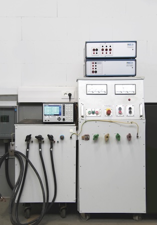
Figure 4. Conventional testing system up to 500A with variable transformer, top right the Power Choke Tester DPG10-4000B/F with 3-Phase Extension Unit in comparison. Image used courtesy of Bodo’s Power Systems [PDF]
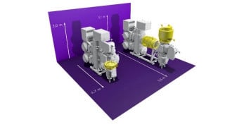
Figure 5, furthermore, shows the old direct current linearity test bench developed in the early 1990s by Hans von Mangoldt GmbH. It is a thyristor-based system housed in four cabinets and capable of 5000 A. In comparison, the Power Choke Tester DPG10-4000B/F with the 3-phase extension unit EXT2, which replaces this system, can be seen in the foreground on the lower floor of the cart. The size comparison is remarkable and demonstrates the advantage of the DPG10, which can be used for mobile applications at any time. The DPG10 can replace both systems, contributing to the standardization of equipment and streamlining operations.
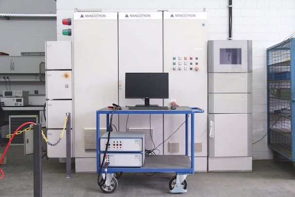
Figure 5. Control cabinets of the DC linearity test bench in the background, in front trolley with DPG10-4000B/F and PC. Image used courtesy of Bodo’s Power Systems [PDF]
The versatility of the Power Choke Tester DPG10 is particularly noteworthy. It is suitable for inductance measurements across a wide power range and can reliably test a wide variety of product groups. The DPG10 delivers precise and reproducible measurement results, whether small sine filter chokes with inductances of a few microhenries or smoothing reactors weighing several tonnes with several hundreds of millihenries are being tested. This range is of central importance to Hans von Mangoldt GmbH, as company’s product diversity continues to grow and the demands on measurement technology increase accordingly.
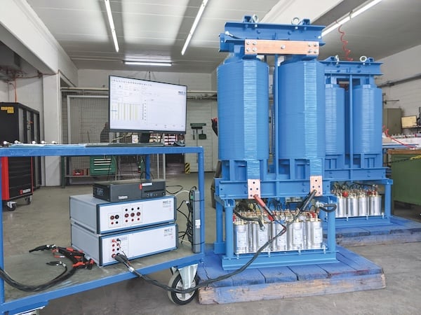
Figure 6. Mobile usage in production. Image used courtesy of Bodo’s Power Systems [PDF]
Another advantage of the Power Choke Tester DPG10 is its mobility. Thanks to its compact dimensions and low weight, the device can be easily used at different production stations. This enables immediate quality control in the production process, saving valuable time. At the same time, the effort of training employees is reduced, as the operation is intuitive and user-friendly.
A locking contact enables door switches to be monitored, allowing testing to be performed by electrically unqualified personnel within a test cabin. This eliminates the need to transport the product to a separate test facility, as was previously required, and paves the way for final testing at the end of the assembly line.
A software API enables the DPG10 to be controlled from a custom software environment, allowing seamless integration into tailored process chains. This was also a key criterion for Hans von Mangoldt GmbH, as numerous product characteristics, beyond inductance, are recorded during the final inspection and documented using an in-house developed software system. This ensures that every product is tested in accordance with the customer-specific requirements. The software guides the operator through every step of the testing process, ensuring that no measurement is overlooked.
Fully automated testing of mass-produced wound components using the new InterfaceBox INT1
PCB-mounted wound components or wound components for the automotive industry are manufactured in extremely large quantities. These cost-sensitive products are, therefore, often manufactured on fully automated production lines.
With the new InterfaceBox INT1, inductance measurement can now be performed on a fully automated production line without the need to develop custom software to control the Power Choke Tester DPG10.
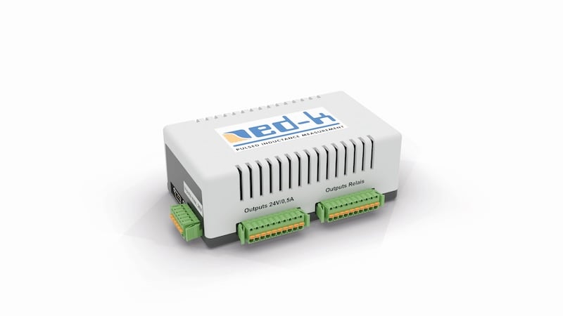
Figure 7. InterfaceBox INT1 to enable fully automated inductance testing in the production line. Image used courtesy of Bodo’s Power Systems [PDF]
The InterfaceBox INT1 provides the interface between the Power Choke Tester PC software and a fully automated production line. Three universal inputs and five universal outputs enable the interaction with the production line’s PLC. For example, the PLC can signal the DPG10 software that:
- a new test item has been contacted or a new measurement can be started
- the production line has been stopped
Furthermore, the DPG10 software can signal the production line PLC via five universally configurable outputs that:
- a measurement is in progress
- the limit curve test has failed (FAIL, part is rejected)
- the DPG10 system is ready for a new measurement
- the measurement is completed, and the test item can then be ejected from the test line
Warning lights, horns, or foot switches can also be connected. The active 24 VDC outputs deliver up to 12 W per output. Relay outputs (250VAC/8A or 30VDC/5A) are also available.
All inputs and outputs are individually configurable via the software, meaning each output can be assigned a separate activation delay and activation time. The existing functions can be assigned to any output.
Summary
In a market defined by rapid change and rising expectations, Hans von Mangoldt GmbH has made a strategic decision to adopt the Power Choke Tester DPG10 from ed-k. A move that underscores its commitment to innovation and quality. The collaboration of Hans von Mangoldt GmbH with ed-k has proven to be particularly effective, driven by a shared vision: to develop cutting-edge solutions that streamline manufacturing processes while upholding the highest quality standards of precision and reliability. This technology choice positions Hans von Mangoldt GmbH to meet future challenges with confidence and agility and underscores ed-k’s market leadership in the field of pulsed inductance measurement.
This article originally appeared in Bodo’s Power Systems [PDF] magazine and is co-authored by Hubert Kreis, Chief Executive Officer, ed-k, and Robert Rohn, Development, Hans von Mangoldt GmbH