Facebook
 Google
 GitHub
 Linkedin
Introduction to Quartz Crystal Oscillators
This article focuses on quartz crystal oscillators to introduce engineers to the equivalent model of the quartz crystal, quartz crystal impedance against frequency, crystal reactance against frequency, series and parallel resonant frequency, quartz crystal calculations, and available types of quartz oscillators configurations.
Frequency stability is a significant feature of any given oscillator. A good oscillator must be able to inject constant frequency output under varied load environments.
Quartz crystal oscillators have received much attention due to their ability to overcome the electric challenges that have affected the frequency stability of oscillators, including changes to the oscillator's direct current input power voltage, temperature variations, and load variations.
Oscillation is the repeated variation in current or voltage in a given electrical circuit that results in a periodic waveform. The number of times the cycle is repeated per second gives the oscillation frequency. The electronic device that produces oscillation is known as an oscillator.
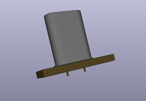
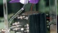
Figure 1. The quartz crystal oscillator. Image used courtesy of Simon Mugo
Equivalent Model of the Quartz Crystal

Figure 2. The actual and equivalent model of the crystal quartz. Image used courtesy of Simon Mugo
The equivalent circuit model above is a series RLC circuit, which in this case represents the crystal’s mechanical vibrations, which are in parallel with an added capacitance, Cp, the representation of the connections to the quartz crystal. Quartz crystals have a series resonance which forms parts of their operational parameter.
The equivalent impedance operates with a series resonance where inductance Ls resonates with the capacitance Cs at the operating frequency of the crystal, known as the crystal series frequency, fs. Besides series frequencies, the established second frequency results from the Ls and Cs parallel resonance with capacitor Cp.
Quartz Crystal Impedance Against Quartz Crystal Frequency

Figure 3. Crystal frequency against crystal quartz. Image used courtesy of Simon Mugo
R = R and XLS = 2fLs
\(X_{CS}=\frac{1}{2\pi fC_{s}}\,and\,X_{CP}=\frac{1}{2\pi fC_{p}}\)
\(Z_{S}\sqrt{R_{S}^{\,\,\,\,\,2}+(X_{LS}-X_{CS})^{2}}\)
\(Z_{P}=\frac{Z_{s}\times X_{CP}}{Z_{S}+X_{CP}}\)
From the crystals impedance slope above, it is evident that increase in frequency across the terminals at a specific frequency, the series inductor Ls and capacitor Cs interactions create a series RLC circuit that reduces the impedance of the crystal to the minimum equal to Rs. The frequency point is referred to as series resonant frequency fs. Below this frequency, the crystal becomes capacitive.
If the frequency goes beyond this series resonant point, the quartz crystal has the behavior of an inductor until the point where the crystal reaches the parallel point frequency, fp. At the fp, the interaction between the Ls and capacitor Cp forms an LC tank circuit that is parallel tuned, and here impedance across quartz crystal is at maximum.
From the discussion, quartz crystal is a fusion of parallel and series-tuned resonant circuits that oscillate at the parallel point and series point frequencies having small differences between them. They depend on the point of cut of the given crystal. The quartz crystal can be operated in either parallel or series frequencies, but they cannot be operated in both frequencies at once.
Quartz crystals can be operated as either an inductor, capacitor, parallel resonance, or series resonance circuit. This can be further demonstrated by the crystal’s reactance against frequency.
Quartz Crystal Reactance Against Quartz Crystal Frequency

Figure 4. Reactance against frequency graph. Image used courtesy of Simon Mugo
From the graph
XS = R2 + (XLS- XCS) 2
\[X_{CP}=\frac{-1}{2\pi fC_{p}}\]
\[X_{P}=\frac{X_{s}\times X_{CP}}{X_{S}+X_{CP}}\]
From the reactance against frequency slope in the graph above, we can take note that series reactance at fs is inversely proportional to the capacitance, Cs because above fp and below fs the quartz crystal seems to be capacitive. Again, note that between fs and fp the crystal seems to be inductive as the two given parallel capacitances cancel each other out. The formula for the quartz crystal series resonance frequency is
\[f_{s}=\frac{1}{2\pi\sqrt{L_{S}C_{S}}}\]
Parallel resonance frequency will only occur under the condition that series LC leg reactance is equal to parallel capacitor reactance as shown in the equation below
\[f_{p}=\frac{1}{2\pi\sqrt{L_{S}(\frac{C_{P}C_{S}}{C_{P}+C_{C}})}}\]
Example Calculations
Problem
A certain quartz crystal oscillator has the listed values: Cs = 0.09972pF, Rs = 6.4 ohms, and Ls = 2.546mH. If the capacitance across capacitor Cp is 28.68pF, find the crystal’s oscillating frequency and its secondary resonance.
Solution
Start by calculating the series resonant frequency of the crustal, which is determined by:
\[f_{s}=\frac{1}{2\pi\sqrt{L_{S}C_{S}}}\]
\[f_{s}=\frac{1}{2\pi\sqrt{2.546mH\times0.09972pH}}\]
fS = 9.987MHz
The crystal’s parallel resonant frequency is determined by:
\[f_{p}=\frac{1}{2\pi\sqrt{L_{S}(\frac{C_{P}C_{S}}{C_{P}+C_{C}})}}\]
\[f_{s}=\frac{1}{2\pi\sqrt{2.546mH(\frac{28.68pF\times0.09972pF}{28.68pF+0.09972pF})}}\]
fp = 10.005MHz
From the calculations when you take the difference between the series fundamental frequency and the parallel fundamental frequency you get 18kHz which is very small. However, at this frequency range, the Quality Factor of the quartz crystal due to inductance being more than the capacitive is extremely high.
Calculate the series resonance frequency of the crystal using:
\[Q=\frac{X_{L}}{R}=\frac{2\pi fL}{R}=\frac{2\pi\times9.987\times10^{6}\times0.002546}{6.4}\]
Q = 24966 or 25,000
The Q-Factor of the crystal quartz is about 25000, and the higher Xl/R factor has contributed this. The range of the Q-Factor for most crystals is between 20000 and 200000 compared to the best LC-tuned tank circuit with a Q-Factor of less than 1000. The high Q-factor is important as it also makes the crystal very stable. The high stability is what makes them suitable for the construction of circuits for crystal oscillators.
Quartz Crystal Oscillator Configurations
Colpitts Quartz Crystal Oscillator

Figure 5. Colpitts quartz crystal oscillator. Image used courtesy of Simon Mugo
The configuration is designed using a common collector amplifier. The role of resistors R1 and R2 is to set the direct current bias level at the base while the resistor RE sets the level for the output voltage. The resistor R2 should be set as large as possible to serve as a preventive measure to the crystal connected parallel to it.
The connected transistor 2N4265 is an NPN with switching above 100 MHz, higher than the crystal, which ranges between 1 and 5 MHz. From the configuration, capacitors C2 and C1 shunt the transistor output to reduce the amount of feedback signal. Therefore, the capacitor C1 and C2 maximum values are limited by the transistor’s gain. For the avoidance of power dissipation in excess, ensure that you keep the output amplitude low.
CMOS Crystal Oscillator

Figure 6. CMOC crystal oscillator. Image used courtesy of Simon Mugo
This type of crystal operates through series resonance frequency. Initially, it is biased into its by a feedback resistor R1 in its operating region center. The action will ensure that the Quality factor point of the used inverter is a high gain region. The R1 value is 1 M Ohms. It is important to ensure that the value of R1 is over 1 M Ohm.
The biggest benefit of this type of crystal oscillator is its ability to readjust itself and maintain 360 degrees oscillation phase shift. Unlike the previously discussed oscillators that give a sinusoidal waveform output, this transistor, due to utilization of the digital logic gate, gives a square waveform output that oscillates between low and high. Its operating frequency fluctuates depending on the switching features of the logic gate used.
Pierce Crystal Oscillator

Figure 7. Pierce crystal oscillator. Image used courtesy of Simon Mugo
Here, the crystal XT determines the oscillating frequency. Series resonance frequency is the frequency in which it operates. This creates a low impedance between the input and output. The crystal is used in most digital timers, clocks, and watches. In the circuit, R1 is used to control the feedback amount.
Microprocessor Crystal Oscillator
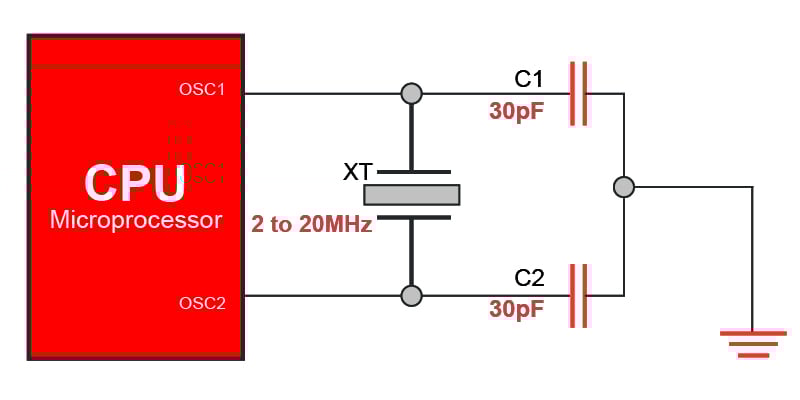
Figure 8. Microprocessor crystal quartz oscillator. Image used courtesy of Simon Mugo
Most microcontrollers and microprocessors have pins labeled OSC1 and OSC2. These are the oscillator pins of the IC used to connect to the quartz crystal that is externally located. Sometimes the pins connect to ceramic resonators and standard RC networks of the oscillator. This type of oscillator produces a square waveform that is continuous. It is applied in system timing and master clocks.
Key Takeaways of Quartz Crystal Oscillators
- Oscillation involves repeated variation in current or voltage in a specific electrical circuit resulting in a periodic waveform.
- A quartz crystal equivalent combines the parallel and series RLC circuit.
- Quartz crystal can be operated in both series and parallel resonance.
- The crystal impedance formula has been derived as \(Z_{P}=\frac{Z_{s}\times X_{CP}}{Z_{S}+X_{CP}}\) for parallel crystal impedance and \(Z_{S}=\sqrt{R_{S}^{\,\,\,\,\,2}+(X_{LS}-X_{CS})^{2}}\) for series impedance.
- The reactance formula is \(X_{S}=R_{S}^{\,\,\,\,\,2}+(X_{LS}-X_{CS})^{2}\) for series reactance and \(X_{P}=\frac{X_{s}\times X_{CP}}{X_{S}+X_{CP}}\) for shunt reactance.
- Four types of quartz crystal oscillator configurations exist: CMOS, microprocessor, pierce, and Colpitts.
Featured image used courtesy of Adobe Stock