Facebook
 Google
 GitHub
 Linkedin
Resonance Explained
This article introduces resonance and how it is related to impedance and admittance, the parallel and series RLC circuit resonant design, calculations of its parameters and electrical quantities, and the application of the resonance circuits.
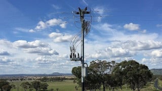
In electric circuits, there are energy-storing elements like capacitors and inductors. The energy-storing elements are what cause resonance. Resonance is the driving concept behind the working principle of TV and radio receivers, allowing viewers to select desired frequencies for their TV channels.

Image used courtesy of Adobe Stock
Electrical Resonance
For electrical resonance to occur, there must be a cancelation of admittances and impedances of the elements of the circuit at a given resonant frequency. In some special circuits, this can only occur when the impedance between the output and input of the system is about zero and its transfer function is closer to one.
There exist two types of resonance that are series and parallel. These configurations exist based on how elements of the circuits are connected–in either series or parallel. This article presents a wider scope of series and parallel resonance.
Series Resonance
In this type of resonance, all the circuit passive elements are connected in series in what we refer to as a series RLC circuit. Look at the series RLC circuit in Figure 1 below with values represented in the phasor domain.

Figure 1. Series Resonance Circuit. Image used courtesy of Simon Mugo
The inductor, resistor, and capacitor which form part of the passive elements are connected in series with the sinusoidal voltage source which serves as the input;
Apply Kirchoff’s Voltage Law around the given loop in the circuit:
\[V-V_{R}-V_{L}-V_{C}=0\]
Replacing the values of the inductor, resistor, and capacitor in the above equation gives:
\[V-IR-I(jX_{L})-I(-jX_{C})=0\]
Rearranging the equation:
\[V=IR+I(jX_{L})+I(-jX_{C})\]
Further rearrangement:
\(V=I[R+j(X_{L}-X_{C})]..........\)(1)
Note that equation 1 above is in the form of V = IZ and therefore, the impedance Z is shown by the equation below:
\[Z=R+j(X_{L}-X_{C})]\]
Electrical Quantities and Parameters at Resonance
The series RLC resonance circuit will have several parameters and electrical quantities when at resonance and it shall be very significant if we derive them in this article.
Resonant Frequency
This is the frequency at which resonance occurs and is denoted as fr. When you have a series RLC circuit, resonance when the impedance Z term is equal to zero that is the difference between the value of XL – XC gives us zero.
Equating the above to zero gives us:
\[X_{L}=X_{C}\]
Substituting \(X_L = 2\pi fL\) and \(X_{C}=\frac{1}{2\pi fC}\) in the equation above gives,
\[2\pi fL=\frac{1}{2\pi fC}\]
Making f the subject of the formula gives:
\[f=\frac{1}{(2\pi)\sqrt{LC}}\]
This translates to the resonance frequency of the series RLC circuit which can be written as:
\[f_{r}=\frac{1}{(2\pi)\sqrt{LC}}\]
Where C is the capacitor's capacitance and L is the inductor's inductance.
While the series RLC resonant frequency is independent of the resistor R, it always depends on the capacitance C and inductance L.
Impedance
From earlier derivations, we found that impedance Z of the series RLC circuit is given by:
\[Z=R+j(X_{L}-X_{C})]\]
But
\[X_{L}=X_{C}\]
And substituting this in the impedance Z equation, we get
\[Z=R+j(0)\]
Hence
\[Z=R\]
This explains that the impedance Z of the series RLC circuit is equal to the resistance R in the circuit.
Current I Flowing Through Series RLC Circuit
Earlier we derived equation (1) as
\[V=I[R+j(X_{L}-X_{C})]\]
Let’s substitute XL=XC into the equation.
Therefore,
\[V=I[R+j(0)]\]
\[V=IR\]
Making I the subject of the form gives
\[I=\frac{V}{R}\]
And this is the current flowing through the series RLC circuit at resonance.
In the series RLC circuit, the impedance arrives at the minimum value at resonance. Therefore, the maximum current of the series RLC circuit is attained at resonance.
Voltage Across Resistor
The voltage that goes across the resistor is given by the formula
\[V_{R}=IR\]
Let us substitute the value of I in the equation
\[V_{R}=(\frac{V}{R})R\]
Canceling R out we find that
\[V_{R}=V\]
And that gives as the voltage across the resistor
Voltage Across Capacitor
From the circuit above, the voltage across the capacitor is given by:
\[V_{C}=I(-jX_{C})\]
Substituting the current I value in the equation
\[V_{C}=\frac{V}{R}\Big(-jX_{C}\Big)\]
Opening the bracket
\[V_{C}=-j\Bigg(\frac{X_{C}}{R}\Bigg)V\]
But we know that \(\frac{X_{C}}{R} = Q-Factor\),Hence, the equation becomes
\[V_{C}=-jQV\]
And this is the voltage across the capacitor at resonance.
The magnitude of the voltage across this capacitor at resonance can be found to be
\[|V_{C}|=QV\]
Voltage Across Inductor
This is given by
\[V_{L}=I(jX_{L})\]
By substituting the value of I in the equation;
\[V_{L}=\frac{V}{R}(jX_{L})\]
Rearranging
\[V_{L}=j\Bigg(\frac{X_{L}}{R}\Bigg)V\]
Hence
\[V_{L}=jQV\]
And this gives the voltage across the inductor at resonance.
The magnitude across the inductor at resonance will be
\[|V_{L}|=QV\]
It is significant to take note that series resonance RLC circuits are named voltage magnification circuits because both the magnitude of the voltage across the capacitor and inductor is equal that voltage is equal to Q times the input voltage V.
Parallel Resonance
This is the resonance that occurs on the parallel RLC circuit. Let’s look at the parallel RLC circuit below which has a phasor domain representation.
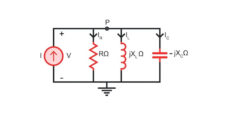
Figure 2. Series Parallel Resonance Circuit. Image used courtesy of Simon Mugo
In this circuit, it is evident all the passive elements’ connection is in parallel with the input sinusoidal current source.
We have labeled node P in the same circuit and can write the nodal equation at this point.
\[-I+I_{R}+I_{L}+I_{C}=0\]
By introducing the value of currents across the elements into the equation.
\[-I+\frac{V}{R}+\frac{V}{jX_{L}}+\frac{V}{-jX_{C}}=0\]
Rearranging the above equation, we get:
\(I=V\Bigg[\frac{1}{R}+j\Bigg(\frac{1}{X_{C}}-\frac{1}{X_{L}}\Bigg)\Bigg]..........\)Equation 1
The equation above is of form I = VY
Where Y is the admittance of the parallel RLC circuit.
Therefore, admittance will be given by:
\[Y=\frac{1}{R}+j\Bigg(\frac{1}{X_{C}}-\frac{1}{X_{L}}\Bigg)\]
Resonance Electrical Quantities and Parameters of the RLC Circuits
Here, we will focus on the derivation of electrical quantities and parameters of the parallel RLC circuits at resonance.
Resonant Frequency
Here, resonance occurs when the term of the imaginary admittance is zero.
\[\frac{1}{X_{C}}-\frac{1}{X_{L}}=0\]
Rearranging you get
\[X_{L}=X_{C}\]
Note that the above resonance condition is similar to the RLC circuit, implying that the resonance frequency fx remains the same.
\[f_{r}=\frac{1}{(2\pi)\sqrt{LC}}\]
Admittance
From the derivation of equation 1, note that admittance is given by:
\[Y=\frac{1}{R}+j\Bigg(\frac{1}{X_{C}}-\frac{1}{X_{L}}\Bigg)\]
But at resonance
\[X_{L}=X_{C}\]
Substituting it in the admittance equation we get
\[Y=\frac{1}{R}\]
Therefore, at resonance, we have the admittance Y being equal to the resistance reciprocal.
Voltage Available Across Each Element
We know that \(\frac{1}{X_{C}}-\frac{1}{X_{L}}=0\) and by replacing this into equation 1, find that
\[I=\frac{V}{R}\]
Rearranging
\[V=IR\]
This gives the voltage across the element in the parallel RLC resonance circuit.
Current Through the Resistor
This is given by the formula
\[I_{R}=\frac{V}{R}\]
But we already know the value of voltage as V=IR and can substitute it
Hence,
\[I_{R}=I\]
And this gives us the current flowing through the resistor at resonance.
Current Through Inductor at Resonance
This is given by
\[I_{L}=\frac{V}{jX_{L}}\]
Let’s substitute the value of V in the equation above
\[I_{L}=\frac{VR}{jX_{L}}\]
On rearranging, we get
\[I_{L}=-j\Bigg(\frac{R}{X_{L}}\Bigg)I\]
But \(\frac{R}{X_{L}}\) is the Quality factor, Q of the system hence current flowing through the inductor becomes
\[I_{L}=-jQI\]
Therefore, the magnitude of this current flowing through the inductor will be given by:
\[|I_{L}|=QI\]
Current Through the Capacitor
This is given by:
\[I_{C}=\frac{V}{-jX_{L}}\]
Substituting the value of V in the equation gives
\[I_{C}=j\Bigg(\frac{R}{X_{C}}\Bigg)I\]
Hence,
\[I_{C}=jQI\]
Which is the current flowing through the capacitor at resonance.
The magnitude flowing through the capacitor is given by:
\[|I_{C}|=QI\]
The parallel RLC electrical circuits are also known as current magnification circuits because the magnitude of the electrical current that flows through the capacitor and inductor is equal to the quality factor times the current at the input.
Applications of Resonance
- Television broadcasts and radio transmissions
- Voltage magnification especially the series RLC circuit
- Communication systems and signal processing
- Oscillator circuits
- Induction heating
Key Takeaways of Resonance
- In circuits, there exist energy-storing elements such as capacitors and inductors.
- There exist two types of resonance that are series and parallel RLC circuit resonance.
- Resonance is about the cancellation of admittance and impedances in an electrical circuit.
- The article has introduced us to how to calculate the electrical quantities and parameters of both series and parallel RLC circuits.