 Facebook
 Google
 GitHub
 Linkedin
Impedance and Reactance
Impedance and reactance
An element in a DC circuit can be described using only its resistance. The resistance of a capacitor in a DC circuit is regarded as an open connection (infinite resistance), while the resistance of an inductor in a DC circuit is regarded as a short connection (zero resistance). In other words, using capacitors or inductors in an ideal DC circuit would be a waste of components. Yet, they are still used in real circuits and the reason is that they never operate with ideally constant voltages and currents.
As opposed to constant voltage circuits, in AC circuits the impedance of an element is a measure of how much the element opposes current flow when an AC voltage is applied across it. It is basically a voltage to current ratio, expressed in the frequency domain. Impedance is a complex number, which consists of a real and an imaginary part:
![]()
where Z is the complex impedance. The real part R represents resistance, while the imaginary part X represents reactance. Resistance is always positive, while reactance can be either positive or negative. Resistance in a circuit dissipates power as heat, while reactance stores energy in the form of an electric or magnetic field.
Impedance of a resistor
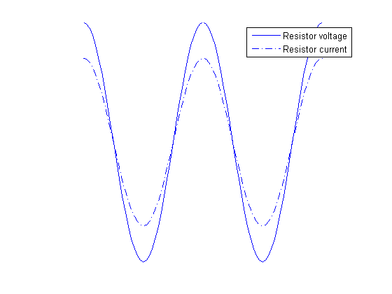
Resistors in AC circuits behave the same way they do in DC circuits. Basically, the impedance of a resistor consists only of the real part, which is equal to the resistance of the resistor. Therefore, the impedance of a resistor can be expressed as:
![]()
where Z is the impedance, and R is the resistance of the resistor. It is obvious that a resistor has no reactance, and can therefore store no energy. Also, when a voltage is applied across the resistor, the current flowing through the resistor will be in phase with the voltage, as can be seen in this illustration:
Impedance of a capacitor
Capacitors are components which introduce a certain capacitance into a circuit. They are used to temporarily store electrical energy in the form of an electric field. While this definition is technically correct, it doesn’t mean much to a hobbyist or even to most engineers. It is perhaps more appropriate to say that capacitors are used to lag the voltage by 90 degrees compared to the current, in the time domain. This effect is better described graphically:
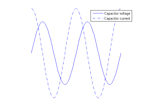
As can be seen from the graph, the voltage of a capacitor lags behind the capacitor current. Alternatively, it can be said that the capacitor current leads capacitor voltage by 90 degrees. In order to represent this fact using complex numbers, the following equation is used for the capacitor impedance:
![]()
where ZC is the impedance of a capacitor, ω is the angular frequency (given by ω=2πf, where f is the frequency of the signal), and C is the capacitance of the capacitor. Several facts are obvious from this formula alone:
- The resistance of an ideal capacitor is infinite.
- The reactance of an ideal capacitor, and therefore its impedance, is negative for all frequency and capacitance values.
- The effective impedance (absolute value) of a capacitor is dependent on the frequency, and for ideal capacitors always decreases with frequency.
Impedance of an inductor
Similarly, inductors are components which introduce a certain inductance into a circuit. They are used to temporarily store electrical energy in the form of a magnetic field. Therefore, inductors are used to lag the current by 90 degrees compared to the voltage, in the time domain. The following graph explains this phenomenon:
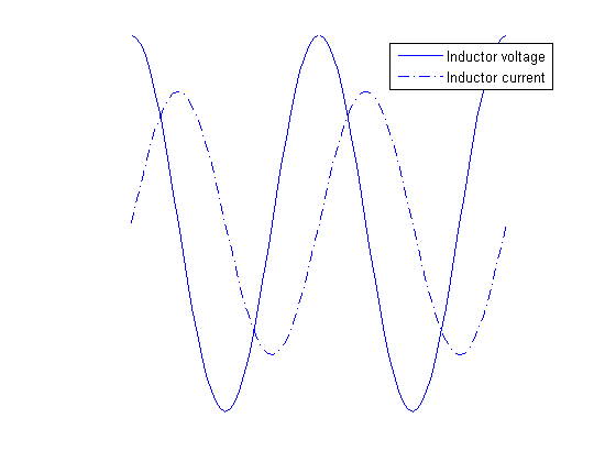
The voltage of an inductor leads the capacitor current by 90 degrees. The following equation is used for the impedance of an inductor:
![]()
where ZL is the impedance of the given inductor, ω is the angular frequency, and L is the inductance of the inductor. Again, several conclusions can be drawn from this formula:
- The resistance of an ideal inductor is zero.
- The reactance of an ideal inductor, and therefore its impedance, is positive for all frequency and inductance values.
- The effective impedance (absolute value) of an inductor is dependent of the frequency and for ideal inductors always increases with frequency.
Ohm’s law
Ohm’s law was originally formulated for DC circuits, and it states:
![]()
To make sense for AC circuits, it was later expanded with the use of complex numbers, and the new formulation is:
![]()
where U is the complex voltage between two points, I is the complex current, and Z is the complex impedance. Since impedance is always regarded as a complex number, we have omitted the underscore for the impedance throughout this text.
The notion of complex voltages and currents can be confusing at first, so let’s try to explain this first. AC circuits are often in a steady state, where there are one or more power sources operating at the same frequency, giving a sinusoidal output. In this case, it can be proven that all the voltages and currents in the circuits are also sinusoidal waveforms oscillating, all of them oscillating at the same angular frequency, ω. However, these voltages and currents are not in phase, generally speaking. If the voltage in an AC circuit is given as a cosine wave such as this one:
![]()
where u(t) is the voltage between some two points in a circuit given as a function of time, UM is the amplitude, ω is the angular frequency, and ΦU is the phase, then the complex representation of this voltage is:
![]()
On a circuit-wide scale, it is common to use one signal as the phase-reference signal. This means that it is assumed that the phase of that signal is zero, and phases of all other signals (voltages and currents) are determined in regard to that reference.
Equivalent impedances
Connection in series
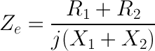
If two impedances are connected in series, the equivalent impedance is obtained by simple addition - Ze=Z1+Z2. The addition of two complex is easily perfomed like this:
![]()
![]()
For example, a 10 Ω resistor connected in series with a 1mF capacitor at 100Hz will have the equivalent impedance of:
![]()
The effective impedance, also called the magnitude of the impedance is calculated as:
![]()
In our example, the magnitude of the impedance equals:
![]()
Connection in parallel
To obtain the equivalent impedance of two impedances connected in parallel, we will first define admittance. The unit of admittance is a siemens [1 S] and it is the measure of how easily an element will allow current to flow, and its value is the inverse of impedance:

The equivalent admittance of two impedances connected in parallel is equal to the sum of individual admittances:
![]()
If we use the same values as in the previous example, we can easily obtain:
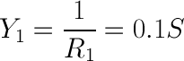
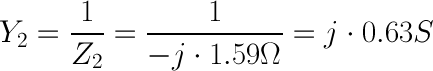
![]()
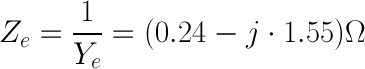
This gives the impedance magnitude of:
![]()