Facebook
 Google
 GitHub
 Linkedin
Introduction to Transmission Line Insulator Design
Learn about the basic characteristics and design parameters for insulators in overhead transmission lines.
Check out Part 1 of this article series.
Insulators play a dual role in overhead transmission systems. They electrically isolate live conductors from grounded structures (towers and poles) and mechanically support the physical weight and tension of the conductors under varying environmental and operational conditions. The performance of insulators must account for dielectric strength, mechanical integrity, weathering resistance, and contamination tolerance. Otherwise, insulator failure can result in flashover, power outages, or catastrophic structural failure.
Construction and Materials
When choosing an insulator, it’s important to consider line voltage, mechanical loading, geometry of installation, and environmental factors. Four principal types of insulators are used in overhead transmission systems:
- Pin-type insulators are commonly used in distribution systems up to 33 kV. These are rigidly mounted on crossarms and carry the conductor on top. Their mechanical simplicity limits their use in high-voltage applications due to flashover risks and limited creepage distance (a parameter we’ll discuss later on in the article).
- Suspension-type insulators are the most widely used for high-voltage transmission (above 33 kV and up to UHV). These consist of disc-shaped units connected in series by metal hardware to form an insulator string. The number of discs in a string scales with system voltage and pollution severity. The suspension configuration allows for flexibility under wind and mechanical loading, distributing stress more evenly.
- Strain insulators are a variant of suspension insulators used at dead-end towers or angle points where conductors are subject to high tensile forces. Their primary function is mechanical: they must resist lateral loads while maintaining electrical insulation.
- Shackle insulators are used in low-voltage applications and urban installations where compact design and both vertical and horizontal mounting are needed. Due to their limited size and strength, they’re restricted to short spans and low voltages.
Insulators are typically fabricated from one of three classes of materials:
- Porcelain.
- Toughened glass.
- Polymer/composite.
Table 1 provides the characteristics of each material.
Table 1. Insulator materials.
| Material | Dielectric Strength | Mechanical Strength | Weight | Pollution Resistance | Key Weakness |
| Porcelain | High | High | Heavy | Moderate | Brittle fracture |
| Toughened Glass | Very High | High | Heavy | Low–moderate | Impact sensitivity |
| Polymer/Composite | Moderate–High | Very High (Flexible) | Light | High | Aging, moisture ingress |
Porcelain, a form of ceramic, is composed of kaolin, quartz, and feldspar sintered at high temperatures. In addition to the high mechanical strength noted in Table 1, it has long-term aging stability and is resistant to UV and tracking. However, it’s prone to brittle fracture under impact or due to manufacturing defects such as voids or microcracks. Its heavier weight also increases tower loading. Porcelain insulators often have glazed surfaces to improve water repellency.
Toughened glass insulators offer improved dielectric strength. When broken, toughened glass shatters into small fragments, reducing the risk of flashover. Its transparency also increases the visibility of internal defects. The main drawback of a toughened glass insulator is susceptibility to mechanical damage during handling or from vandalism, particularly in exposed rural lines.
Polymer insulators, also known as composite insulators, are constructed with a fiberglass core rod, silicone rubber or EPDM housing, and metal end fittings. These insulators offer significant weight reduction, excellent hydrophobicity, and resistance to pollution-induced flashover. However, they’re more susceptible to ultraviolet aging, moisture ingress at interfaces, and long-term degradation under acidic or high-ozone environments. Note that design and field inspection are more critical for composites, as possible internal failures won’t be externally visible.
Creepage Distance
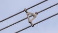
Creepage distance—the shortest path along the insulator surface between the high-voltage terminal and ground—is a fundamental design parameter in high-voltage insulation. It’s illustrated in Figure 1.
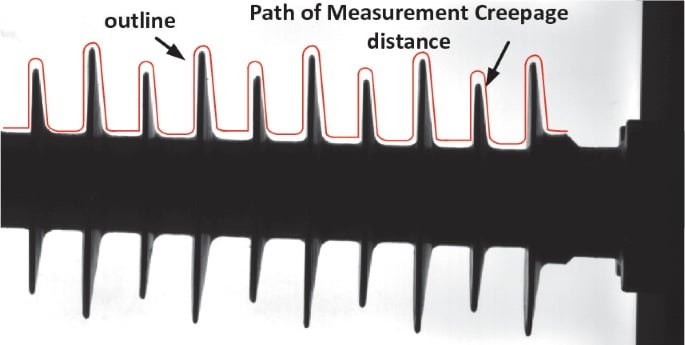
Figure 1. Creepage distance over a transmission line insulator. Image used courtesy of Lin Nie
Creepage distance determines the insulator’s resistance to surface flashover, especially under polluted or wet conditions where contaminants reduce surface resistivity. For standard environments, a typical creepage requirement is 20–25 mm/kV (rms). In heavily polluted or coastal areas, this can rise to 31–40 mm/kV or more.
The insulator profile is engineered to maximize creepage while preventing water bridges that promote tracking. For instance, fog-type insulators use closely spaced sheds with steep profiles to repel moisture. Polymer insulators leverage their inherently hydrophobic surfaces to achieve comparable performance with shorter creepage paths.
Creepage requirements are defined in the IEC 60071 and IEC 60815 standards. These standards take into account pollution severity, altitude, and service conditions.
Mechanical and Electrical Design
Insulators are rated based on both mechanical and electrical performance. For porcelain and glass insulators, the mechanical rating is typically the Specified Mechanical Load (SML). For composites, it’s specified by the Tensile Load (TL) or Mechanical Failing Load (MFL). These loads must accommodate safety margins along with the combined effect of conductor tension, wind pressure, and ice loading.
Electrically, insulators must withstand power frequency overvoltage, lightning impulse, and switching surge voltages. Standard test parameters include:
- Power frequency withstand voltage (dry and wet).
- Impulse withstand and flashover voltage.
- Leakage current measurements in the presence of pollution.
Pollution performance is classified as light, medium, heavy, or very heavy. These levels are defined in IEC 60815. Selection of insulators must account for these pollution classes to ensure proper insulation coordination. For example, in highly polluted zones, RTV (room-temperature vulcanized) silicone coatings are applied to porcelain insulators to enhance hydrophobicity and reduce flashover risk.
Maintenance requirements vary by material. Porcelain and glass insulators require regular washing in polluted areas, especially where hydrophilic films form. Composite insulators typically require less maintenance but demand periodic inspection for surface erosion, bonding integrity, and sheath cracks. Diagnostic tools such as UV cameras and leakage current sensors help detect insulator degradation early.
Key Takeaways
Together with conductor specifications, insulator characteristics determine how well a transmission line can do its job under adverse conditions and its ability to maintain mechanical integrity over time. Insulators, which are made from materials such as porcelain, glass, or polymer, are chosen based on environmental durability and electrical performance. Different types—pin, suspension, strain, and shackle—serve different mechanical roles, and their design considers creepage distance, pollution exposure, and mechanical load to prevent flashovers and maintain reliability.
Countinue reading this article series wtth Part 3: "Design Requirements of Transmission Line Towers."
Featured image used courtesy of Adobe Stock