Facebook
 Google
 GitHub
 Linkedin
Introduction to Conductors for Transmission Lines
This article examines how the design, construction, and placement of conductors influence the performance of overhead transmission lines.
Here, we kick off Part 1 of our Transmission Line Components and Design article series.
Transmission line conductors are responsible for carrying electrical energy over long distances with minimal loss. The performance of a transmission system heavily depends on these critical components. In this article, we’ll discuss several key characteristics of transmission line conductors that must be taken into consideration during the design or selection process.
Materials and Construction
Overhead transmission lines are most often constructed from one of the following:
- Aluminum Conductor Steel Reinforced (ACSR).
- All-Aluminum Conductor (AAC).
- All-Aluminum Alloy Conductor (AAAC).
- Copper.
Table 1 provides some relevant information about each construction type.
Table 1. Four types of conductors.
| Conductor Type | Electrical Conductivity (MS/m) | Tensile Strength (MPa) | Corrosion Resistance | Relative Cost | Typical Use Case |
| ACSR | ~35 (aluminum) | 300–500 (with steel core) | Moderate | Low | Long-distance HV lines |
| AAC | ~35 | ~120–160 | Low | Low | Urban/short span |
| AAAC | ~32–34 | ~200–300 | High | Medium | Coastal areas, medium spans |
| Copper | ~58 | ~200–250 | Moderate | High | Distribution lines (rare) |
All four options present a trade-off between conductivity, mechanical performance, and cost. For example, copper has a higher electrical conductivity than AAC (approximately 58 MS/m, versus 35 MS/m for aluminum at 20 °C). However, it’s rarely used in high-voltage transmission systems due to its higher weight, cost, and susceptibility to theft.
Though the conductivity of copper is technically higher, AAC’s lower density gives it a better conductivity-to-weight ratio. This makes it a more favorable material for suspended spans. However, because it lacks tensile strength, AAC is only suitable for short spans or low-voltage networks.
ACSR, which consists of high-conductivity aluminum strands wound around a central core of high-tensile galvanized steel, is by far the most prevalent of the options under discussion. Thanks to its composite structure, it provides excellent mechanical strength suitable for long spans and high-tension lines while still maintaining reasonable electrical performance.
Last but not least, AAAC offers a balanced solution. It incorporates aluminum alloy strands that provide better strength and corrosion resistance than AAC without the added complexity of a steel core.
Figure 1 illustrates four aluminum-based conductor types, including the three we discussed above.
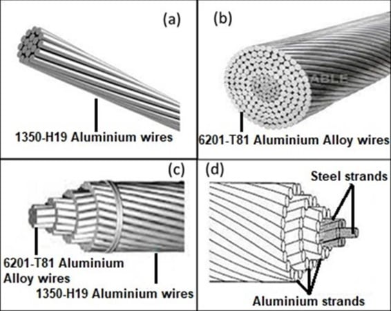
Figure 1. Some common transmission conductor types: AAC (a), AAAC (b), ACAR (c), ACSR (d). Image used courtesy of MDPI
Configuration
Transmission lines are typically configured as either single or bundled conductors per phase. While single conductors are sufficient for lower voltage levels, extra high voltage (EHV) and ultra-high voltage (UHV) lines often employ bundled conductors. These consist of two or more sub-conductors isolated at uniform intervals using spacers. Bundling reduces the electric field intensity at the conductor surface, minimizing corona losses and radio interference, which become pronounced at voltages above 230 kV.
Phase configuration usually follows the three-phase AC standard, with balanced phase spacing to minimize mutual inductance and achieve symmetrical impedance. In some systems, transposition towers are employed to cyclically rotate phase positions, thereby equalizing inductive coupling over long distances. Phase spacing is determined by factors such as line voltage, corona discharge limits, insulation coordination, and right-of-way constraints.
Current-Carrying Capacity
The ampacity of a conductor is the maximum current it can carry continuously without exceeding temperature limits that would compromise its mechanical integrity or safety clearances. This capacity is governed by the thermal balance between ohmic heating (I²R losses), radiative and convective heat loss, and solar heat absorption. Ampacity can be described by the following equation:
$$I_{max}~=~\sqrt{\frac{q_c~+~q_r~-~q_s}{R(T)}}$$
Equation 1.
where:
qc is the convective heat loss
qr is the radiative heat loss
qs is the solar heat absorption
R(T) is the resistance of the conductor at the operating temperature (T).
Standards such as IEEE Std 738 provide empirical methods for calculating the current-temperature relationship of overhead lines. These methods incorporate parameters such as wind speed, ambient temperature, solar incidence, and emissivity.
Derating is applied under adverse environmental conditions such as high ambient temperature, low wind speeds, or dense urban heat zones, which can hinder heat dissipation. Modern grids employ advanced real-time thermal rating (RTTR) systems to dynamically adjust ampacity based on sensor data.
Sag and Tension
Conductor sag directly affects the vertical clearance of the line from the ground, a critical safety and regulatory constraint. This is illustrated in Figure 2.
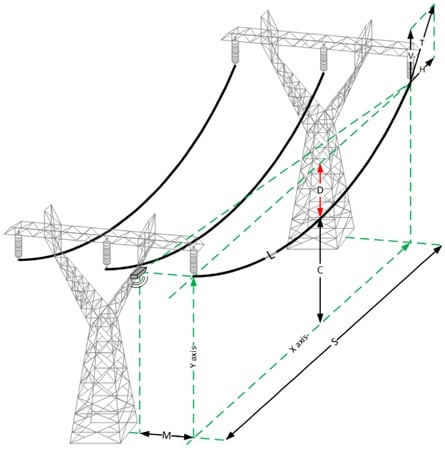
Figure 2. Effect of sagging on transmission line clearance from ground. Image used courtesy of MDPI
The sag is a function of conductor tension, span length, ambient temperature, and the conductor’s thermal expansion characteristics. The catenary equation approximates the sag for moderate span lengths:
$$D~=~\frac{w L^2}{8T}$$
Equation 2.
where:
D is sag
w is weight per unit length
L is span length
T is horizontal tension.
More advanced models such as the Creep-Elastic Tension-Sag (CETS) method account for time-dependent creep in aluminum, which causes permanent elongation over the conductor’s life. As specified by standards like NESC or IEC 60826, designs must also consider ice and wind loads.
Under high current flow, conductors heat up and expand, increasing sag and potentially violating ground clearance requirements. Thermal sag under emergency conditions can be substantial. Because of this, conductor operating temperatures must remain below 90–100 °C for standard conductors, and up to 200 °C for high-temperature low-sag (HTLS) conductors. These HTLS options use composite cores or aluminum-zirconium alloys, reducing sag and increasing ampacity.
Key Takeaways
Understanding conductor design is essential when working with real-world transmission systems, where both electrical performance and mechanical reliability are constantly tested by environmental and loading conditions.
Along with phase spacing, conductor configurations—whether single or bundled—influence power flow and electromagnetic behavior. Ampacity and ambient conditions determine thermal limits, while sag and tension calculations are used to maintain ground clearance and mechanical balance. Finally, it’s necessary to consider trade-offs between conductivity, weight, and strength (not to mention cost) when choosing the materials from which the conductor is constructed.
Continue reading this article series with Part 2 - Introduction to Transmission Line Insulator Design.
Featured image used courtesy of Adobe Stock