Facebook
 Google
 GitHub
 Linkedin
Introduction to Fuel Cell Emulators
Read on to learn more about what a fuel cell emulator is and how it works.
Fuel cells are devices that convert the chemical energy of a fuel directly to electrical energy. They are a clean energy source and have high energy storage capability. In recent years, the use of fuel cells in multiple applications has gained traction. The standalone aspect of distributed resource technology makes fuel cells useful resources where the areas are not powered by the power grid or the grid is unreliable and backup power is necessary.
Fuel cell emulators can be used in various types of fuel cell control-related studies.
What Is a Fuel Cell Emulator?
A fuel cell power supply system comprises a fuel cell stack, a fuel supply system, a power electronics-based inverter and a master controller [2]. The fuel cells typically produce DC output voltage which is a function of the load current value and the fuel flow rate.
It is important to note that the fuel cell voltage varies directly as the value of supplied fuel flow rate, whereas it is indirectly proportional to the load current [1]. The entire system is well-integrated, so the inverter's characteristics and response from the master controller enhance the overall system performance.
Choosing the Right Fuel Cell
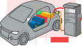
Fuel cells have a wide range of applications compared to other energy conversion technologies and are useful for systems of a few watts to multiple megawatts. The most common applications include transportation, portable power supply and distributed power generation [1]. It is one of the most promising renewable power sources because of its high power density and low emission.
There are six commercially available types of fuel cells–alkaline, direct methanol (DM), molten carbonate, phosphoric acid, proton exchange membrane (PEM) and solid oxide (SO) [2]. Based on the specific application, the appropriate fuel cell type is chosen based on the advantages offered.
For instance, PEM fuel cells are mostly used in automotive applications, while SO fuel cells are employed for stationary power sources. SO fuel cells are attractive for distributed power applications at the industrial level because of their high power density and high-grade waste heat that may be utilized in cogeneration applications. DM fuel cells are used as portable power sources as they do not require any fuel processing and operate at low temperatures. However, PEM fuel cells are placed anywhere in the distribution system, thus a good candidate for distributed generation. In addition, since they do not have any pollutants but have high power density, reliable power at steady-state and quick start ability, PEM fuel cells are attractive for vehicular applications.
How Fuel Cell Emulators Work
Fuel cells produce electricity from a simple electrochemical reaction in which an oxidizer and a fuel react to form a water product for a typical fuel cell [1]. The fuel is mostly hydrogen, while the oxidizer is oxygen from the air. The oxygen continually passes over the cathode while the hydrogen passes over the anode to generate electricity with heat and water as by-products. Since there are no moving parts in the fuel cell, it is a quiet and reliable power source.
The schematic diagram of a sample PEM fuel cell is shown in Figure 1.

Figure 1. Schematic diagram of a PEM fuel cell. Image property of EETech
A sample fuel cell emulator implementation with power stage and control stage is shown in Figure 2.
The power stage of the fuel cell emulator comprises a current source converter (buck rectifier) which has high power capability with a small ripple DC link and a DC/DC buck converter [2]. The two power electronic circuits and a DSP-based controller provide voltage current fuel cell characteristics along with output voltage and current. It can function in all three operating regions - activation, ohmic and concentration.
The power stage has AC at the input and generates DC at the output, which follows the V-I characteristic of fuel cells. At the front end, the two line-to-line input voltages are sensed for control synchronization. The output voltage and load current from the buck converter are measured to control the output DC voltage. The user supplies the fuel flow rate command for the buck rectifier. The outputs from the controller are switching signals for the buck rectifier's six switches and the buck converter's switch.

Image property of EETech

Figure 2. Power stage and control stage for a sample fuel cell emulator. Image property of EETech
Key References
1. Ahmad et al., A simple PEM Fuel Cell Emulator using Electrical Circuit Model, 2010
2. Siriroj et al., The Modeling and Control of Fuel Cell Emulators, 2008