Facebook
 Google
 GitHub
 Linkedin
How To Bring Ultra Precise Current Measurement to All Use Cases—Not Just DC
What are the challenges in power measurement and efficiency calculation? DCCT current transducers are hundreds of times more accurate than standard Hall-effect transducers commonly used for current control in frequency converters. Unfortunately, they are also significantly more complex in design. This story looks at the applications and provides a look at using DCCTs in test benches.
This article is published by EEPower as part of an exclusive digital content partnership with Bodo’s Power Systems.
Article co-authored by LEM's Joern Burk.
Broadband precision power meters digitize voltage and current signals. The sampled values u(t) and i(t) are multiplied together. The arithmetic mean of the resulting power curve p(t), averaged over one or more fundamental periods, yields the active power P. The accuracy of power measurement depends on the amplitude accuracy of the voltage and current samples, the time delay between these samples, and the precision of the measurement interval or zero-crossings used to determine the period length.
The first frequency converters appeared in the late 1960s. It took over 20 years before measurement devices were available that could handle the extremely steep voltage edges and distorted current signals of converters. One example is the LEM NORMA Power Analyzer D 6000 from the early 1990s. At that time, current measurement was done using very broadband coaxial shunts and the so-called GUARD technique, which minimized common-mode interference. Common-mode currents from the measurement channel to the device housing are generated by measuring very steep voltage edges at high potential, resulting in amplitude and phase angle errors.
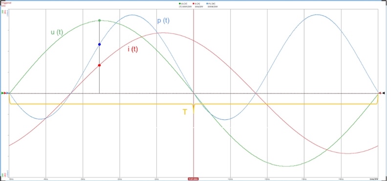
Figure 1. Active power calculation. The two signals u(t) and i(t) must be sampled and multiplied absolutely simultaneously. The accuracy of the active power depends on the amplitude accuracy of the sampled values, the time delay between voltage and current sampling (phase error), as well as on the errors in determining the averaging interval T. Image used courtesy of Bodo’s Power Systems [PDF]
Losses Cannot Be Measured Directly
Another challenge in measuring losses in frequency converters and electric motors is their high efficiency and the fact that losses cannot be measured directly. Loss calculation for these drive components is always based on input and output power. For an inverter, this means electrical DC power at the input and electrical AC power at the output. For an electric motor, it’s electrical input power and mechanical output power.
While individual active power values can be measured with reasonably high accuracy, the uncertainty in loss measurement must consider that errors in input and output power measurements may go in opposite directions – e.g., input power measured too high and output power too low. Thus, the uncertainty in loss measurement is highly dependent on the component’s efficiency. It’s easy to see that for inverters with nearly 99 % efficiency, measurement errors can result in more than 100 % deviation in actual losses. Therefore, power meters and sensors of the highest accuracy must be used for loss calculations in drive components.
As already mentioned, external coaxial shunts used to be quite suitable for these measurements in terms of amplitude accuracy and phase fidelity. However, measuring the small voltage drop at the shunt output on a high and very distorted voltage signal was highly problematic. The connected measuring device had to have exceptionally high common-mode rejection. In addition, external high-current coaxial resistors were very expensive.
For many years now, ultra-precise DCCT current transducers – galvanically isolated from the measurement signal – have been used to extend the measurement range of power meters. This technology was originally developed to regulate linear DC high-current sources in particle accelerators. One early application in medical technology was magnetic field measurement in MRI scanners.
High DC accuracy alone is not sufficient to precisely calculate losses in an inverter. The transducers must maintain amplitude accuracy across a wide frequency range up to several hundred kHz and must not introduce additional phase shifts between the actual voltage and current signals. Such shifts would alter the power factor and lead to errors in active power and loss calculations.
Comparison of Old and New Transducer Generations. The first mass-produced DCCT transducers were not yet optimized for measuring higher-frequency AC currents. This may be one reason it took so long for these sensors to gain traction in extending the measurement range of power meters. Additionally, the older generation of transducers had relatively high sensitivity to external AC fields. Today, however, they have become standard.
Specialized transducers now cover frequency ranges from DC up to several MHz. These are typically only needed for very high-frequency applications, such as signal analysis of new, fast semiconductor switches. In these cases, switching frequencies can approach 100 kHz, and with very low-inductance loads, the harmonics of the switching frequency can theoretically extend into the MHz range.
For typical power and loss measurements, such a wide frequency range is not necessary. The impedance in the measurement circuit significantly attenuates most high-frequency components in the current. And if there are no frequency components in the current, there will be no active power components at that frequency either, because only signal components of voltage and current at the same frequency generate active power or losses.
DCCT current transducers are hundreds of times more accurate than standard Hall-effect transducers commonly used for current control in frequency converters. Unfortunately, they are also significantly more complex in design. In the past, two identical inductors were required to measure the DC component of the current.
The second inductor was used solely to compensate for disturbances caused by the first inductor in the main core. These inductors had to be manufactured with extreme precision and uniformity. This report does not delve into the exact workings of the old analog technology.
In developing the latest generation of DCCT transducers, LEM used its expertise in microprocessor-controlled error compensation from other current measurement technologies. In the new IN series, the second inductor for noise suppression has been eliminated.
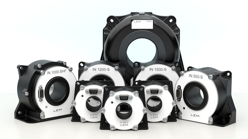
Figure 2. LEM high precision IN range. Image used courtesy of Bodo’s Power Systems [PDF]
Disturbances caused by the inductor used for DC measurement are learned during the production process, digitized, stored in the processor, and then compensated via a D/A converter, an analog amplifier, and a compensation winding in the main core. Hardly any error-prone analog components are needed in the transducer anymore. Even offset adjustment is stored in the FPGA. The typical DC accuracy of the latest transducers is in the low single-digit ppm range. LEM has patented this new technology.
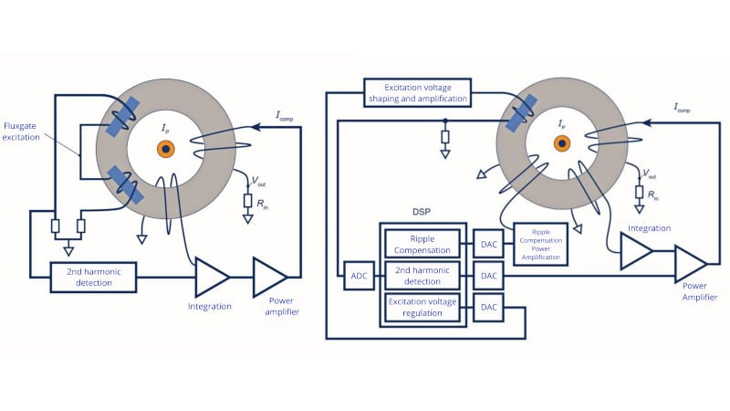
Figure 3. Conventional analog DCCT and new technology with FPGA compensation. Image used courtesy of Bodo’s Power Systems [PDF]
Transducers are now also developed with AC optimization in mind. Here too, LEM uses its knowledge of DC/AC current transducers suitable for converter applications. In the AC circuit, DCCT transducers differ only slightly from standard current-compensated Hall-effect transducers.
Simplifying the Use of Transducers in Test Benches
Testing high-voltage batteries in production environments has historically been complex. To simplify the use of transducers in test benches, a dedicated transducer power supply is required. This should ensure stable operation as well as high-precision signal integrity of the connected transducers and burdens.
To meet these challenges, SIGNALTEC, which specializes in broadband power measurement technology, developed its Single- and MultiChannel Transducer Systems (MCTS), both featuring galvanically isolated power supply channels. SIGNALTEC has established a well-equipped measurement and testing lab where development-stage amplitude and phase accuracy measurements can be performed across a wide frequency range.
Extensive accessories allow the transducer output signals to be adapted to all types of current or voltage inputs on measuring devices.
Integrating transducers into automation systems often requires specialized signal digitization, particularly in end-of-line battery manufacturing test setups. High-precision and fast EtherCAT converters can provide this functionality in real time. These converters have evolved significantly from the first models.
The first so-called EtherCAT converter could only measure current and provided an EtherCAT protocol at the output. The latest systems, such as Powerlens from REDCUR, developed in collaboration with SIGNALTEC, now offer complete current and voltage measurements, EtherCAT output, and additionally support a CAN protocol.
DCCT transducers have become the standard for extending the measurement range of wideband power analyzers, with digitally compensated DCCT transducers that are aimed to deliver ever more accurate results in both DC and AC current measurement.
Together with its partners, SIGNALTEC and REDCUR, LEM has committed to the field of ultra-precise DCCT current sensors. SIGNALTEC provides AC-optimized CT transducers along with the accessories needed for easy integration into test benches, while REDCUR delivers complete measurement systems for testing high-voltage batteries in production environments.
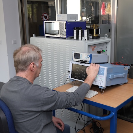
Figure 4. Testing high-voltage batteries. At the high-frequency test bench, amplitude and phase deviations of the transducers can be measured up to a frequency of 500 kHz. Reference standards are coaxial shunts and pulse current transformers. Image used courtesy of Bodo’s Power Systems [PDF]
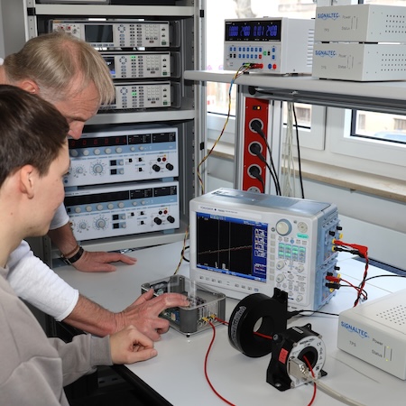
Figure 5. Using a 1000 A pulse current source, the time delay through the transducer is measured. Image used courtesy of Bodo’s Power Systems [PDF]
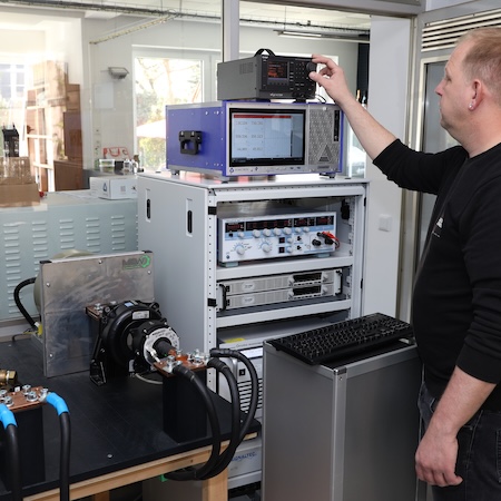
Figure 6. At the high-power test bench, DC power and AC low-frequency power with variable power factor can be simulated up to 1200 V and 2000 A. Image used courtesy of Bodo’s Power Systems [PDF]
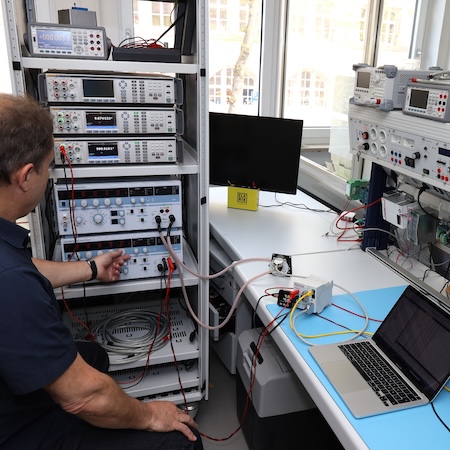
Figure 7. Adjustment of the Powerlens measurement system. Image used courtesy of Bodo’s Power Systems [PDF]
This article originally appeared in Bodo’s Power Systems [PDF] magazine and is co-authored by Horst Bezold, CEO, Signaltec, and Jörn Burk, Head of Industrial Sales for DACH and Eastern Europe, LEM