Facebook
 Google
 GitHub
 Linkedin
Determining Phase and Line Voltages and Currents in Wye-connected Generators
A generator that produces three separate sinewave output voltages with 120° phase differences is called a three-phase generator. The three generator coils may be connected in one of two possible configurations: Y-connection and Δ-connection. In this article, you’ll learn how to determine phase and line voltages and currents in wye-connected generators.
To complement?? this article, we provide you with the Delta-Wye Calculator.
The output voltage levels produced by a three-phase generator depend on the connection arrangement of the three individual generator loops (or coils). The two possible connection methods are wye (Y) and delta (Δ) because of circuit resemblances to those symbols.
Phase Voltages and Currents
Figure 1 represents a Y-connected three-phase generator, in which the coil terminals a, b, and c are connected to a single neutral terminal (N). There are four output terminals: A, B, C, and N.
The system illustrated in Figure 1 is termed a three-phase four-wire supply. In some cases, the neutral conductor may not be connected, and the system becomes a three-phase three-wire supply.
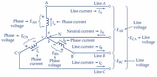
Figure 1. For a Y-connected three-phase generator, the phase voltage and phase current are the output voltage and current from each coil. The line voltage is the voltage measured between any two output lines (conductors). The line current is the current flowing in a line. Image used courtesy of Amna Ahmad
All three coils in a three-phase generator are identical, producing the same level of rms output voltage. This is termed the phase voltage(Vp). Figure 1 shows EAa, EBb, and ECc, now identified as EAN, EBN, and ECN, respectively. All three are equal to Vp.
The phase current (Ip) is the current level supplied by each of the three generator coils. The directions of the phase currents (Ia, Ib, and Ic) shown in Figure 1 are those that occur when each coil has a positive output voltage. Thus, the phase current for coil Aa is shown flowing out of terminal A and into a.
Double Subscript Notation
The double subscript notation is used with the voltage symbols to indicate the direction of current flow when each coil (or loop) output is positive. Subscript Aa used with voltage EAa identifies terminal A as positive concerning terminal a when this coil output is positive. EAa is rewritten as EAN in Figure 1, indicating that terminal A is positive concerning the neutral terminal while the coil output is positive.
Similarly, when the output of coil Bb is a positive quantity, terminal B is positive concerning b, and the internal current direction is from b to B. The voltage is identified as EBb or EBN in Figure 1. The voltage labeled ECc, or ECN, shows that terminal C is positive concerning c when coil Cc has a positive output. In a different subscript system, the order of the double subscripts indicates the current direction instead of the voltage polarity.
Line Currents and Voltages
The conductors that connect a three-phase generator to a load are referred to as lines, and the current carried by each of these conductors is known as the line current(IL). Figure 1 shows that the phase and line currents in a Y-connected generator are the same quantities.
The neutral conductor is the return conductor for all three individual coils in a Y-connected, four-wire system. So, the neutral current (IN) is the phasor sum of all three line currents. This would seem to make IN larger than IL and therefore require a neutral conductor that is thicker than the line conductors. However, in Example 1, it is demonstrated that when all three coils have identical loads (a balanced load), IN is zero. When a balanced load condition does not exist, current flows in the neutral conductor.
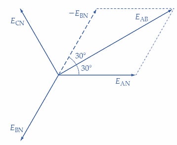
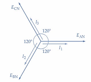
In a Y-connected generator, the phase voltage is the voltage measured between any line and neutral. The line voltage is the voltage measured between any two lines. Thus, the line voltage is the phasor difference of two phase voltages. Figure 2 demonstrates how the line voltages are calculated.

(a) Phasor diagram for voltages
(b) Line voltage EAB is the phasor difference EAN - EBN
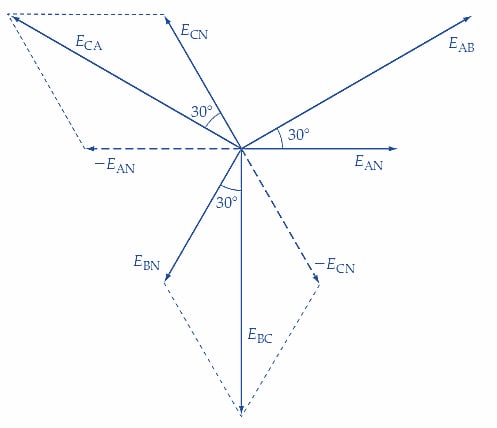
(c) Line voltage EBC = EBN - ECN and ECA = ECN - EAN
Figure 2. For a Y-connected three-phase generator, the line voltages are the phasor sums of pairs of phase voltages. This makes each line voltage equal to 3 (phase voltage). Image used courtesy of Amna Ahmad
Figure 2(a) shows the individual coil voltage phasors. Line voltage EAB in Figure 1 is the phasor difference between EAN and EBN. To determine EAB, -EBN is first drawn equal and opposite to EBN [see Figure 2(b)]. Because of the 120° phase difference between EAN and EBN, there is a 60° angle between EAN and -EBN. Voltages EAN and EBN are equal in magnitude; therefore, phasors EAN and –EBN are equal in length. Because of this equality, phasor EAB (representing the sum of EAN and -EBN) is situated 30° from EAN and 30° from -EBN, as illustrated in Figure 2(b).
This gives,
\[E_{AB}=E_{AN}cos30°+{\large(}-E_{BN}cos30°{\large)}\]
which is the same as,
\[E_{AB}=V_{p}cos30°+V_{p}cos30°=2{\Large(}V_{p}cos30°{\Large)}=1.732V_{p}\]
or
\[E_{AB}=\sqrt{3V_{p}}\]
So, for a Y-connected generator,
\[Line\,Voltage=\sqrt{3}\times Phase\,Voltage\]
that is,
\(V_{L}=\sqrt{3}V_{p}\) (1)
Also,
Line Current = Phase Current
or
\(I_{L}=I_{p}\) (2)
Figure 2(b) also shows that line voltage EAB leads phase voltage EAN by 30°. Figure 2(c) shows the determination of EBC and ECA as the phasor differences EBN-ECN and ECN-EAN, respectively. Note that for line voltage EAB, the subscript indicates that the generator terminal A is positive with respect to terminal B when EAB is a positive quantity (see Figure 1).
Y-Connected Loads
The circuit of a Y-connected generator with Y-connected load resistors is shown in Figure 3 (a). Note that the generator phase voltages are once again identified as EAN, EBN, and ECN, and the load voltages are similarly identified. The reasoning that developed Equations 1 and 2 for a Y-connected generator can also be applied to determine the voltage and current relationships for the Y-connected load.
Referring to Figure 3 (a), the voltages across the individual loads are obviously equal to the generator phase voltages. Therefore, Equation 1 can be rewritten as
\[Line\,Voltage=\sqrt{3}\times Load\,Voltage\]
Also, the individual load currents are clearly the same currents that flow in the lines.
Line Current = Load Current
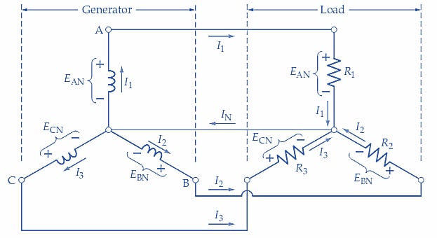
(a) Y-connected three-phase generator with Y-connected resistive loads
(b) Phasor diagram of load voltages and currents for purely resistive loads
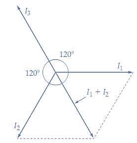
(c) When I1 = I2 = I3, I1 + I2 = -I3, giving I1 + I2 + I3 = 0
Figure 3. Circuit and phasor diagrams for a Y-connected three-phase four-wire generator with a Y-connected balanced load. In this case, the load voltages and currents are equal to the generator phase voltage and phase current. Images used courtesy of Amna Ahmad
Example 1
Load resistors, R1, R2, and R3 in Figure 3(a) are each 100 Ω, and the phase voltage is Vp=100 V. Determine: (a) the line current, (b) the neutral current, and (c) the line voltage.
Solution
(a) The line current
\[E_{AN}=E_{BN}=E_{CN}=100V\]
\[I_{L}=I_{A}=I_{B}=I_{C}\]
\[I_{L}=\frac{V_{P}}{R_{1}}=\frac{100V}{100\Omega}=1A\]
(b) The phasor diagram for the currents is drawn in Figure 3(b). Because the loads are resistive, each load current is in phase with the phase voltages. Figure 3(c) shows that the phasor sum of I1 and I2 equals -I3. So,
\[I_{N}=I_{A}+I_{B}+I_{C}=0\]
(c) The line voltage
\[V_{L}=\sqrt{3}V_{p}=\sqrt{3}\times100V=173.2V\]
Key Takeaways
- A three-phase wye–connected generator produces three separate sinusoidal alternating voltages from three output terminals.
- The terminals are identified as A, B, and C; sometimes, a neutral terminal (N) is also available.
- The three waveforms have 120° phase differences from each other.
- The generator output voltages can be measured as phase voltage and line voltage.
- The phase and line currents in a Y-connected generator are the same quantities.
Featured image used courtesy of Adobe Stock