Facebook
 Google
 GitHub
 Linkedin
Voltage Cells in Series
In this article, learn how to compute the output voltage and current voltage cells connected in series. Also, learn how series-aiding and series-opposing phenomena work in voltage cells.
When one voltage cell's positive terminal is connected to another's negative, the combined output is the sum of the cell terminal voltages, and the cells are said to be in series.
Output Voltage and Current
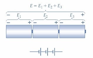
Figure 1(a) shows a battery of four cells connected in series where the negative cell terminal is connected to the positive cell terminal of the previous cell. With this arrangement, the cell voltages are added together for a relatively large battery terminal voltage.
E = E1 + E2 + E3 + E4+ ⋯ (1)
If each cell in Figure 1(a) has an emf of 1.5 V, the total output voltage is,
E = 1.5V + 1.5V + 1.5V + 1.5V = 6V
If the cell EMFs are not all 1.5 V, the output voltage from the battery will still be the sum of the individual cell voltages.
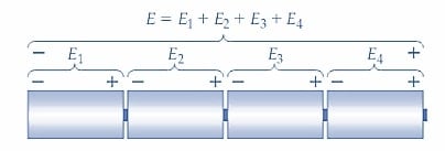
(a) Four series-connected voltage cells
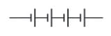
(b) Circuit symbol for four series-connected cells
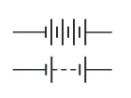
(c) Alternative circuit symbols for series-connected cells
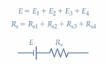
(d) Equivalent circuit for series-connected cells
Figure 1. Series-connected cells with circuit diagrams and equivalent circuits. The output voltage is the total of the individual cell voltages, and the battery’s internal resistance is the sum of the cell’s internal resistances. Images used courtesy of Amna Ahmad
Figure 1(b) shows the circuit diagram for the four cells in series. Alternative ways of graphically representing a battery of series-connected cells are shown in Figure 1(c), and the battery equivalent circuit is illustrated in Figure 1(d). The total internal resistance of the battery of series-connected cells is, of course, the sum of the internal resistances of the individual cells.
Rs = Rs1 + Rs2 + Rs3 + ⋯ (2)
When an external load resistance (RL) is connected to a group of four series-connected cells, the output current is:
\[I=\frac{E_{1}+E_{2}+E_{3}+E_{4}}{R_{L}+R_{s1}+R_{s2}+R_{s3}+R_{s4}}\]
And
I = I1 = I2 = I3 = I4
Note from the circuit that the output current flows through each individual cell. So, for example, if each cell can supply a maximum current of 1 A, the output current from the group of cells cannot exceed 1 A. The open-circuit output voltage, and the output current from the battery, can be calculated from Equations 1 and 3, respectively. The battery’s terminal voltage when supplying a load current is determined by Equation 1. Voltage cells that are not identical can be connected in series; however, the maximum current that the battery of cells can supply is limited to the maximum output of the lowest current cell.
Series-connected cells produce an output voltage equal to the sum of the individual cell voltages and supply a maximum current equal to the maximum that can be taken from the lowest current cell.
Example
The battery shown in Figure 2(a) comprises four individual cells, each with an open-circuit terminal voltage of E =2 V and an internal resistance of 0.1 Ω. Determine the terminal voltage of the battery for no-load and for RL=9.6 Ω. Also, determine the current that flows when the battery terminals are short-circuited.
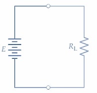
(a) Battery with an external load
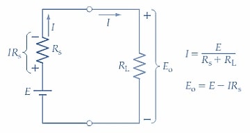
(b) Equivalent circuit
Figure 2. Circuit diagram and equivalent circuit of a battery of cells with an external load. The load current is IE/(Rs+RL), and the battery terminal voltage is Eo= E - (IRs). Images used courtesy of Amna Ahmad
Solution
E = E1 + E2 + E3 + E4 = 4×2V = 8V
Rs = Rs1 + Rs2 + Rs3 + Rs4 = 4 ×0. 1Ω = 0.4Ω
For no-load
Io = 0
And
Eo = E - IoRs = 8V - 0 =8 V
For RL = 9.6Ω
\[I_{o}=\frac{E_{c}}{R_{s}+R_{L}}=\frac{8V}{0.4\Omega+9.6\Omega}=0.8A\]
Eo = Ec - I1Rs = 8V - (0.8A × 0.4Ω) = 7.68V
For short-circuit
RL = 0
\[I_{o}=\frac{E_{c}}{R_{s}+R_{L}}=\frac{8V}{0.4\Omega+0\Omega}=20A\]
Note that short-circuiting a battery or cell terminal should be avoided because it rapidly discharges the cells. Also, the large current that flows could permanently damage rechargeable cells.
9 V Battery
The construction of a commonly-used 9 V battery is illustrated in Figure 3. Six 1.5 V zinc-carbon cells are used, each of which is approximately rectangular prism-shaped. The (negative terminal) bottom of each cell makes contact with the (positive terminal) top of the cell underneath. So the stacked cells are series-connected. The battery-positive terminal connects directly to the top of the uppermost cell, and a flat insulated conductor makes contact from the negative of the bottom cell to the battery-negative terminal.
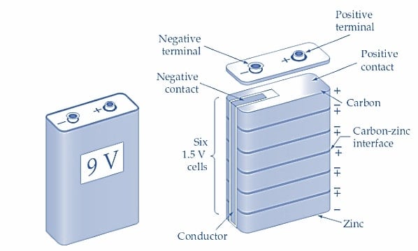
Figure 3. A 9 V battery consists of six 1.5 V cells connected in series. Images used courtesy of Amna Ahmad
Series-Aiding and Series-Opposing Connections
The series cells illustrated in Figure 4(a) each have their positive terminal connected to the adjacent cell's negative terminal. With this arrangement, they assist each other in producing a current flow. The connection method is termed series-aiding. When cells are series-connected to produce currents in opposite directions, as shown in Figure 4(b), the connection is called series-opposing. Series-opposing connections are normally avoided and usually occur only due to the error. The total output voltage is still the sum of the individual cell voltages, but the polarity of the voltages must be considered. As illustrated in Figure 4(c), when one of three 1.5 V cells is connected series-opposing, the resulting terminal voltage of the battery is:
E = E1 + E2 + E3 = 1.5V + 1.5V + (-1.5V) = 1.5V
If a discharged cell is connected in series with fully charged cells, the discharged cell adds little or nothing to the total output voltage, but it does increase the total internal resistance of the battery. So, a discharged cell should not be connected in series with fully-charged cells.
(a) Voltage cells connected in series-aiding sequence
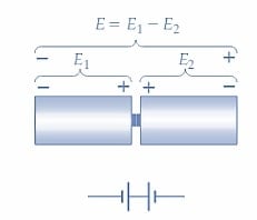
(b) Voltage cells connected in series-opposing sequence
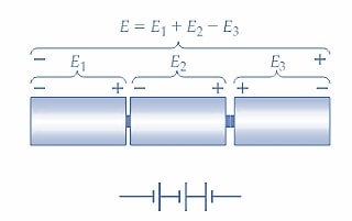
(c) Voltage cells connected in series-aiding and series-opposing sequence
Figure 4. When voltage cells are connected in series, they are always connected series-aiding so that their voltages add together. Cells connected series-opposing give a reduced output voltage. Images used courtesy of Amna Ahmad
Plus/Minus Supply
Figure 5(a) shows two series-connected 4.5 V batteries with their common terminal grounded, and the circuit diagram for the batteries is illustrated in Figure 5(b). Because the negative terminal of the battery B1 is grounded, its output voltage is E1=4.5 V, that is, positive with respect to ground. The positive terminal of B2 is grounded, so the output voltage of B2 is E2=-4.5 V, negative with respect to the ground. The combined output of the two batteries is usually designated ±4.5 V. Many electronic circuits use this plus/minus type of supply.
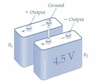
(a) Two batteries connected as a plus-minus supply
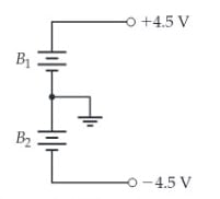
(b) Circuit of plus-minus supply
Figure 5. Two 4.5 V batteries may be connected in series with their common terminal grounded to provide a ±4.5 supply. Images used courtesy of Amna Ahmad
Takeaways of Voltage Cells
A simple voltage cell consists of two different metal plates immersed in a liquid electrolyte. Voltage cells can be operated in series, parallel, or series-parallel combinations. The voltage cell or battery’s performance can be defined in terms of the maximum voltage and current it can supply and its ampere-hour (A-h) rating.
Featured image used courtesy of Adobe Stock