Facebook
 Google
 GitHub
 Linkedin
High-Precision Digital Temperature Sensors Thanks to Wafer-Based Calibration
Power electronics plays a crucial role in modern temperature sensor systems, enabling efficient signal conditioning, energy management, and data transmission.
This article is published by EEPower as part of an exclusive digital content partnership with Bodo’s Power Systems.
Especially in low-power and high-precision temperature sensors, power electronics supports functions such as voltage regulation, pulse-width modulation, and interface compatibility with digital processing units. As temperature sensors are increasingly integrated into power-dense and electromagnetically challenging environments, robust and energy-efficient power electronic design becomes essential for maintaining measurement accuracy and long-term system reliability.
The operating principle of temperature sensors is based on physical effects changing alongside temperature. For example, resistance thermometers use the fact that the resistance of a material changes with temperature. Thermocouples use the Seebeck effect, which generates a voltage when two metals meet at one end and are held at different temperatures. Semiconductor temperature sensors utilise the temperature-dependent change in semiconductor parameters. In the digital low-power temperature sensor SMT172, there are, for example, two BJT-transistors configured as current sources that charge and discharge a capacitor and generate a PWM (pulse width modulation) through a Schmitt-trigger.
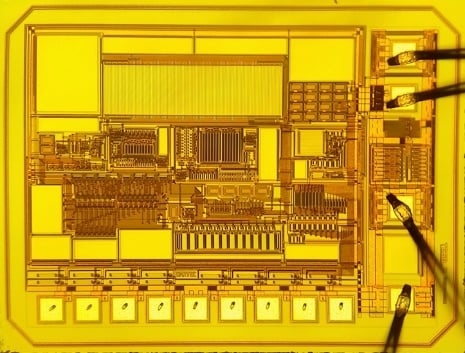
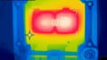
Figure 1. SMT172-Chip 1.3mm x 1.7mm. Image used courtesy of Bodo’s Power Systems [PDF]
After the sensor signal has been transformed into an electric signal, it has to be transmitted in order to make it available for processing and analysis. The transmission can take place wirelessly or wired. In industrial environments, shielded cables are often used to minimize irritations from electromagnetic disturbances. Wireless connection, such as via radio communication, allows a remote surveillance of temperatures in different surroundings.
The transmission of the sensor signal from a temperature sensor for further processing and analysis can be done in two ways: Analogue transmission and digital transmission.
For this, there are special communication protocols like I2C, which can be used for digital communication between sensors and other devices. With analogue transmission, the sensor signal is transmitted in the form of a continuous, non-discrete voltage or current. This signal varies proportionally to the measured temperature. Analogue signals are susceptible to disturbances and distortions, especially over long transmission paths or in areas with electromagnetic influences. Therefore, processing analogue signals requires special circuits in order to avoid quality losses.
A further possibility for lossless data transmission over long distances is pulse width modulation. PWM is a technology that transforms a signal, in this case, the temperature data of the SMT172 sensor, into a digital signal, which is then transmitted.
With pulse width modulation, a periodic signal, a carrier wave, is used for the transmission of information. The information is coded by the width of the impulses in relation to the period length. A longer impulse width signals a higher temperature value, a shorter one a lower.
The temperature sensor continuously collects the temperature and then converts it to digital values. Based on a fixed schematic, the pulse width of the PWM is modulated to transmit the temperature data.
The modulated PWM data is transmitted via a suitable connection, e.g., an electric wire.
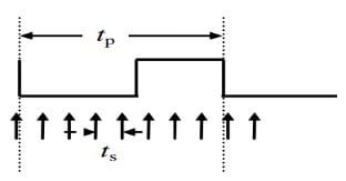
Figure 2. Output signal (PWM) of the SMT172. Image used courtesy of Bodo’s Power Systems [PDF]
A receiver demodulates the data to reconstruct the original temperature value. This is done by measuring the impulse widths and transforming those widths into the respective temperature values based on the predefined modulation schematic.
The receiver can be a conventional microcontroller (e.g., STM32F030F4P6, STM32G031F4P6TR) or a special measuring device. The temperature sensor generates a PWM-signal whose pulse width is proportional to the measured temperature. The microcontroller measures this value and saves it in a register or a variable. On the basis of a given scale or a mathematical formula, the pulse width is converted to a temperature.
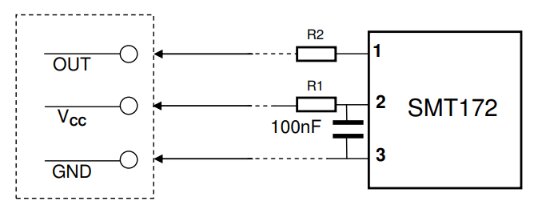
Figure 3. Connection for pulse width modulation. Image used courtesy of Bodo’s Power Systems [PDF]
In temperature sensors, self-heating is a crucial factor that can influence the accuracy of temperature measurements. If a temperature sensor is electrically powered, consumed electrical energy can generate heat and thus falsify the ambient temperature. This self-heating can be minimized by carefully selecting materials, designs, and operating conditions, as in the SMT172. In highly precise applications, it is decisive to take the potential self-heating into consideration and to apply compensation methods. Additionally, self-heating is negligible in the SMT172 by Angst + Pfister because the active current is minimal and the heat emission to the surroundings is maximized by the mechanical construction. Furthermore, the energy efficiency of 0.36 µJ per measurement is record-breaking.
Wafer-based calibration
Wafer-based calibration of temperature sensors is done in multiple steps in order to ensure an excellent and highly precise sensor:
The wafer is being inserted into a special test system, which measures the electric properties of each individual temperature sensor. On a 6-inch wafer, there are around 7000 sensors.
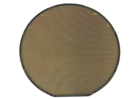
Figure 4. Wafer with 7000 temperature sensors. Image used courtesy of Bodo’s Power Systems [PDF]
The measured electric signals are compared with known reference values to determine the accuracy of the temperature sensor. If there are any deviations determined, the respective correction factors are calculated and applied to the temperature sensor.
At room temperature, the offset of the sensor is determined and compensated by Zener-zapping. After the calibration, the temperature sensor is being evaluated once again to ensure that the correction procedure reached the desired accuracy. After the calibration and validation, the wafer gets cut into single temperature sensors and embedded into different housing variants for protection purposes. The best-known housings are TO18, TO92, TO220, and SOT223.
This wafer-based calibration enables a high absolute accuracy and reproducibility of the temperature sensors since it is done in an automated process, and the single sensors on the wafer are produced under similar circumstances. Thereby, deviations between the single sensors can be minimized. The sensors are thus completely calibrated and aligned. Even after mounting or assembling in a sensor assembly group, the sensors keep their absolute accuracy and don’t have to be aligned again.
This article originally appeared in Bodo’s Power Systems [PDF] magazine.