Facebook
 Google
 GitHub
 Linkedin
Inductors in Parallel
Inductances connected in parallel are analogous to resistors in parallel. Learn more about inductors in parallel here.
For inductances connected in parallel, the effect is analogous to resistors in parallel. The admittances add to produce a total admittance that is the sum of the individual admittances.
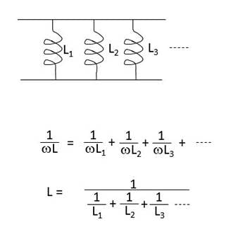
Figure 1. A parallel connection of inductors and the equivalent inductance. Image used courtesy of Blaine Geddes
Derivation
The formula of Figure 1 can be derived as follows:
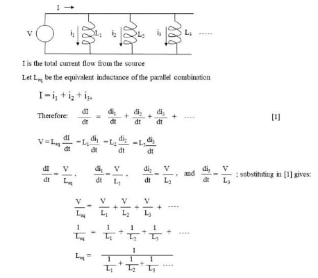
Figure 2. Derivation of the equivalent circuit inductance of a parallel combination of inductors. Image used courtesy of Blaine Geddes
Inductor Applications
In general, inductors are often used as an in-line series filter to limit surge currents or suppress electromagnetic interference, used in parallel with a capacitor to implement a tuned circuit bandpass response (tank circuit), used in combination with capacitors to implement a ladder network filter structure, and used as impedance matching elements to cancel capacitive reactance at a particular frequency. Wiring inductors in parallel is usually not an economical or useful circuit structure, although it may be done to achieve a lower value of inductance for the case of an inductor already present. The case of parallel-connected inductors naturally arises in the case of parallel inductive loads
As can be observed from Faraday’s law, any current-carrying loop will have inductance associated with it. All electrical circuits are current carrying loops, therefore all circuits have some self-inductance, which is usually a parasitic effect and an artifact of forcing a current flow around a circuit. At low frequencies, often the parasitic effect is negligible because the impedance associated with the self-inductance is very low and the wavelengths are very long, so antenna effects are negligible. As the frequency of operation increases, parasitic inductance effects become much more significant.
The principle of electromagnetic induction is exploited to produce a broad range of devices such as solenoids, relays, transformers, motors, and generators. The basic inductive coil is also used as a transducer in the form of a pick-up coil in such devices as magnetic read heads, microphones, phonographs, and engine crankshaft position sensors. A loudspeaker is constructed of a diaphragm attached to an inductive coil that interacts with the field of a permanent magnet to transform an electrical audio waveform into acoustical vibrations.
A solenoid is an inductor with a moveable core forming the mechanical actuator. When a current is applied to the coil, the resulting magnetic field induces a field in the magnetic core slug. The interaction of the applied field and the induced field draws the slug into the coil. When the current is turned off, the electromagnetic force is returned to zero and the slug can be retracted by spring force. That motion makes the solenoid an actuator to achieve a linear mechanical motion by electrical control. A very common example is the solenoid of a starter motor used on internal combustion engines, where the motion of the solenoid is used to slide the pinion gear of the starter motor into mesh with a larger ring gear on the engine flywheel.
A relay is a solenoid where the actuator is used to open and close a set of switch contacts, so a current flow in one circuit is used to gate a current flow in another circuit, thereby allowing a small signal circuit to remotely turn on a high current load.
A transformer is a set of coupled inductors on the same core such that the field of the primary inductor induces a voltage in the secondary inductor, which in accordance with Faraday’s law, will be in proportion to the turns ratio of the secondary to primary windings and can be used to accomplish either a step-up or a step-down voltage change in an AC circuit.
From an equivalent circuit standpoint, an induction motor is a transformer where the coils of the stator form the transformer primary and the induced field in the rotor is the equivalent of the induced field in the secondary winding of the transformer. The rotor of an induction motor is constructed with shorting bars such that the secondary winding is connected to a short circuit. The interaction of the fields of the stator and rotor creates a force that drives the rotation of the machine. The mechanical power developed becomes the electrical equivalent of a resistive load as the electrical energy input is converted to mechanical work.
In an AC generator, a low-power DC excitation voltage is applied to the rotor through slip rings and brushes. The input of rotary mechanical energy to the shaft results in a rotating magnetic field that produces the dΦ/dt that induces the output on the stator coils.
Inductor Design Considerations
A formula for approximating the self-inductance of a uniform cylindrical coil was derived in the introductory chapter of this series and is repeated below.
\(L=\frac{\mu_{0}\mu_{r}N^{2}A}{l}\), where:
μ0 = permeability of free space = 4π x 10-7 H/m,
μr = relative permeability of the core material
N = number of turns of the coil
A = cross-sectional area of the coil
l = length of the coil
The formula was derived assuming a linear magnetic core material (constant μr), cylindrical core, and no flux leakage. For a cylinder some flux leakage occurs at the ends, reducing the formula to an approximation. If the cylinder is folded closed on itself to form a toroid, then no flux leakage occurs at the ends and the formula is quite accurate.
From the formula, the parameters controlling the value of an inductor are the cross-sectional area of the coil, the number of turns, the overall length, and the magnetic permeability of the core. The permeability of the core expresses the degree of magnetization of the ferromagnetic core, which determines the strength of the magnetic field developed in the core. The permeability of the core material is the dominant factor in determining the physical size of the inductor, therefore a high permeability core is desirable. The trade-off is that the highest permeability materials are metals, which are conductors, therefore they have low resistivity. Low resistivity leads to high eddy current losses, which is an I2R effect. Eddy currents are circulating currents in the conductive core created by induced voltage gradients created by the alternating magnetic flux. Eddy currents are minimized by using laminated cores with the highest resistivity possible.
| Material | Composition | Max. Approx. μr | Resistivity (Ω-cm) |
| Iron | 99.8% Fe | 5000 | 10 x 10-6 |
| Silicon electrical steel | 3% Si | 8000 | 47 x 10-6 |
| Grain-oriented silicon electrical steel | 3% Si | 50000 | 50 x 10-6 |
| 4-79 Permalloy | 4% Mo, 79% Ni, bal Fe | 200000 | 58 x 10-6 |
| Supermalloy | 5% Mo, 80% Ni,bal Fe | 450000 | 65 x 10-6 |
| Ferrites |
Various compositions of metal oxides, such as: Fe2O3.MnO Fe2O3.ZO Fe2O3.NiO |
100-4800 | 102 to 108 |
Table 1. Selected properties of common ferromagnetic materials. Image used courtesy of Blaine Geddes
For power line frequencies the most common core material is electrical steel, of which the most expensive grade is grain oriented silicon steel. Grain oriented silicon steel offers the highest permeability of the electrical steels and the highest resistivity, but at the highest cost.
Core losses rise as the frequency of operation rises, so for inductors that operate at higher frequencies, beyond a few kilohertz, ferrites are a very common ferromagnetic core material because they have much higher resistivities than metals, which greatly reduces the eddy current losses in the core. Ferrites are ceramics. They are blends of metal oxides composed mainly of oxides of iron, manganese, zinc, and nickel. Ferrites have much lower permeabilities, but vastly higher resistivities. Because of their lower permeability than the metallic ferromagnetic materials, the physical size of a ferrite core inductor would be much larger than the same inductor designed with a metallic ferromagnetic core, but impedance scales linearly with frequency, so for higher frequencies, lower values of inductance are typically required.
Ferrite materials have been somewhat standardized and are available in prepared blends known by a mix designation number. Table 2 shows some representative commercially available ferrite blends.
| Mix # | Material | Relative Permeability |
| 31 | Fe2O3.MnO.ZO | 1500 |
| 43 | Fe2O3.NiO.ZO | 800 |
| 52 | Fe2O3.NiO.ZO | 250 |
| 61 | Fe2O3.NiO.ZO | 125 |
| 73 | Fe2O3.MnO.ZO | 2500 |
Table 2. Commercially available ferrite blends. Image used courtesy of Blaine Geddes
No inductor is ideal. At high frequencies, the reactance of parasitic capacitance effects between the turns of the coil and the coil to case become significant. For high-frequency considerations, a typical chip inductor can be modelled by the equivalent circuit shown in Figure 3. The parasitic capacitance arises between the individual turns of the coil and from the windings to the case. In parallel with the inductor the parasitic capacitor forms a tank circuit causing the frequency response of the inductor to deviate from ideal as shown in Figure 4.
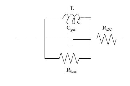
Figure 3. Equivalent circuit model of an inductor. Image used courtesy of Blaine Geddes

Figure 4. Representative frequency response of an inductor. Image used courtesy of Blaine Geddes
Inductor Safety
When the current is suddenly interrupted by an inductor, high voltages are developed. Spark ignitors, such as those used to fire the spark plug in a spark-ignited internal combustion engine use this principle, but it is a problem for switching inductive loads, where repeated arcing of the switch contacts, due to suddenly turning off the inductive load, will erode the contacts over time.
Inductors are wound using magnet wire, which is copper wire with a thin enamel coating. The dielectric breakdown strength of the enamel insulation may need to be considered for high voltage applications.
High temperatures will degrade the enamel coating. Motors commonly fail by overheating, which degrades the enamel coating and can lead to shorting or arcing between the windings.
Featured image used courtesy of Pixabay