Facebook
 Google
 GitHub
 Linkedin
Determining Phase and Line Voltages and Currents in Delta-Connected Generators
A generator that produces three separate sinewave output voltages with 120° phase differences is called a three-phase generator. The three generator coils may be connected in one of two possible configurations; Y-connection and Δ-connection. In this article, you’ll learn how to determine phase and line voltages and currents in delta-connected generators.
As a complement to this article, here is access to the Delta Wye Calculator. Enjoy!
The output voltage levels produced by a three-phase generator depend on the connection arrangement of the three individual generator loops (or coils). The two possible connection methods are wye (Y) and delta (Δ) because of circuit resemblances to those symbols.
Output Voltages and Currents
As an alternative to the Y connection, the individual coils of a three-phase generator may be connected in Δ (delta) configuration.
In the Δ-connected generator shown in Figure 1, the coil terminals are connected A to c, B to a, and C to b. The three output lines are identified as A, B, and C. No neutral conductor is involved.
The line voltage (VL) is the Voltage measured as EAB, EBC, or ECA. The order of the subscripts indicates the terminal polarity when each line voltage is positive. The phase voltage (Vp) is the rms voltage measured across the output terminal of each of the three coils.
It is obvious from Figure 1 that the line voltage and phase voltage are the same quantities in a Δ-connected generator. For a Δ-connected generator
Line Voltage = Phase Voltage
That is,
\(V_{L}=V_{P}\) (1)
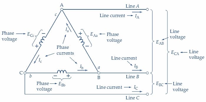
Figure 1. For a Δ-connected three-phase generator, the phase voltage and phase current are the output voltage and current from each coil. The line voltage is the Voltage measured between any two output lines, and the line current is the current flowing in a line. Image used courtesy of Amna Ahmad
The line current (IL) is the current level measured in each of the line conductors. The direction indicated for IL in each line is the direction in which current flows when the line voltage is positive.
When EAB is positive, line A is positive with respect to line B. The direction of line current IA is then out of terminal A, as indicated in Figure 1. Similarly, when B is positive with respect to C, IB flows out of terminal B, and when C is more positive than A, the direction of IC is away from terminal C.
The phase current (Ip) is the current level produced in each of the three generator coils.
Once again, the current directions indicated in Figure 1 are those that occur when each individual coil output is positive. When EAa is positive, Ia flows out of terminal A and into terminal a. When EBb is positive, the Ib direction within the coil is from b to B. Similarly, for ECc, Ic flows from c to C so the output current is out of terminal C and into c.
With the phase currents having the directions indicated in Figure 1, it appears that a circulating current might flow around the coils of a Δ-connected generator. This would not be acceptable because it would produce unnecessary and wasteful power dissipation in the generator coils.
Consider the waveforms in the following figure, and note that at t1:
\[e_{Aa}=E_{m}\]
and
\[e_{Bb}=-0.5E_{m}\]
\[e_{Cc}=-0.5E_{m}\]
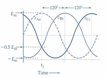
Figure 1-1. Three-Phase Waveforms. Image used courtesy of Amna Ahmad
These instantaneous voltage levels are easily confirmed by calculation as follows:
\[e_{Aa}=E_{m}Sin=E_{m}Sin90°=E_{m}\]
\[e_{Bb}=E_{m}Sin(-120°)=E_{m}Sin(90°-120°)=-0.5E_{m}\]
\[e_{Cc}=E_{m}Sin(90°-240°)=-0.5E_{m}\]
The instantaneous level of voltage producing a circulating current is illustrated in Figure 1 is
\[e=e_{Aa}+e_{Bb}+e_{Cc}\]
At time t1 in Figure 1-1,
\[e=E_{m}-0.5E_{m}-0.5E_{m}=0\]
It is seen that, at time t1, there is no voltage acting around the closed loop formed by the coils. Consequently, there is no current circulating in the coils.
By taking any other instance in the three-phase waveforms illustrated in Figure 1-1, it can be demonstrated that the circulating current is always zero in a Δ-connected generator.
Referring again to Figure 1, note that Ia flows toward terminal A and that both Ic and IA flow away from A.
This gives,
\[I_{a}=I_{A}+I_{c}\]
or, the line current is,
\[I_{A}=I_{a}-I_{c}\]
because the currents are phasor quantities; this is a phasor difference.
Figure 2(a) shows the phasor diagram for the phase currents that a three-phase generator might produce with a balanced load. As explained, when a balanced load occurs, all three line currents are equal and have the same phase relationship to their respective line voltages. If the load consists of three equal Δ-connected resistors, then a balanced load condition exists.
In Figure 2(a), the phasors for the three equal phase currents (Ia, Ib, and Ic) are drawn with 120° phase angle separation. Line current IA is shown in Figure 2(a) as (Ia-Ic) (as determined in the preceding equation). It is seen that Ia and –Ic are separated by 60° and because they are equal in magnitude.
\[I_{A}=I_{a}cos30°+I_{c}cos30°=2(I_{p}cos30°)=1.732I_{p}=\sqrt{3I_{p}}\]
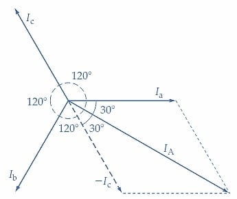
(a) Line current IA is the phasor difference Ia - Ic
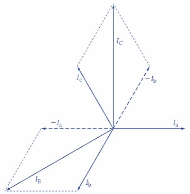
(b) Line current IB = Ib - Ia and IC = Ic - Ib
Figure 2. For a Δ-connected three-phase generator, the line currents are the phasor sums of pairs of phase currents. With a balanced load, each line current is equal to 3 (phase current). Image used courtesy of Amna Ahmad
So, with a balanced load,
\[Line\,Current=\sqrt{3}\times Phase\,Current\]
\(I_{L}=\sqrt{3}\times I_{p}\)(2)
Figure 2(a) also shows that (for a balanced load), the phase current (Ia) leads the line current (IA) by an angle of 30°. In Figure 2(b), the determinations of IB and IC are shown as the phasor differences (Ib-Ia) and (Ic-Ib), respectively.
Delta-Connected Loads
The reasoning used in deriving Equations 1 and 2 for a Δ-connected generator can also be applied to a Δ-connected load. For the circuit in Figure 3(a), the individual Δ-connected load voltages are obviously equal to the line voltages.
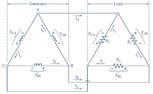
(a) Δ-connected three-phase generator with Δ-connected resistive loads
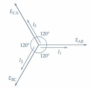
(b) Phasor diagram of load voltages and currents for purely resistive loads
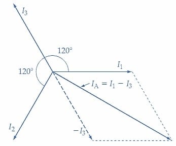
(c) Line current IA is the phasor difference I1 - I3
Figure 3. Circuit and phasor diagrams for a Δ-connected three-phase generator with a Δ-connected balanced load. The load voltage equals the generator phase voltage, and the line current is 3 (load current). Image used courtesy of Amna Ahmad
For a Δ-connected load,
\[Load\,Voltage=Line\,Voltage\]
Also, where all three load impedances are identical, giving a balanced load, the individual load currents combine to produce,
\[Line\,Current=\sqrt{3}\times Load\,Current\]
Example 1
In the circuit shown in Figure 3(a), R1=R2=R3=100 Ω, and Vp=100 V. Calculate the load and line currents.
Solution
From Equation 1,
\[V_{L}=V_{P}=100V\]
Taking voltage EAB as the reference voltage for all phase angles,
\[I_{1}=\frac{E_{AB}}{R_{1}}=\frac{100V}{100\Omega}=1A\angle0°\]
\[I_{2}=\frac{E_{BC}}{R_{2}}=\frac{100V\angle-120°}{100\Omega}=1A\angle-120°\]
\[=1A[cos(-120°)+jsin(-120°)]=-0.5A-j0.866A\]
\[I_{3}\frac{E_{CA}}{R_{3}}=\frac{100V\angle-240°}{100\Omega}=1A\angle-240°\]
\[=1A[cos(-240°)+jsin(-240°)]=-0.5A+j0.866A\]
The phasor diagram for load voltages and currents is drawn in Figure 3(b). Because the loads are purely resistive, the load currents are in phase with the load voltages.
\[I_{A}=I_{1}-I_{3}=1A-(-0.5A+j0.866A)=1.5A-j0.866A\]
\[=\sqrt{1.5^{2}+0.866^{2}\angle tan^{-1}{\Large(}\frac{-0.866}{1.5}{\Large)}}=1.732A\angle-30°\]
Figure 3(c) shows the phasor derivation of IA as I1-I3.
\[I_{B}=I_{2}-I_{1}=(-0.5A+j0.866A)-1A=-1.5A-j0.866A\]
\[=\sqrt{1.5^{2}+0.866^{2}\angle tan^{-1}{\Large(}\frac{-0.866}{1.5}{\Large)}}=1.732A\angle-150°\]
Similarly,
\[I_{C}-I_{3}-I_{2}=(-0.5A+j0.866A)-(-0.54+j0.866A)=0+j1.732A\]
\[=1.732A\angle-270°\]
Key Takeaways: Delta-Connected Generators
- In a three-phase delta-connected generator, three equal phase currents are drawn with 120° phase angle separation
- With a balanced load, each line current is equal to 3 (phase current)
- The line voltage and phase voltage are the same quantities in a Δ-connected generator
Featured image used courtesy of Adobe Stock