Facebook
 Google
 GitHub
 Linkedin
Understanding Corona Discharge in High-Voltage Transmission Lines
The article explores the phenomenon of corona discharge in high-voltage transmission lines and outlines key mitigation techniques.
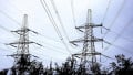
Corona discharge is a localized ionization of air that occurs when the electric field intensity around a conductor exceeds a critical threshold. It manifests as a visible glow—bluish in darkness, as Figure 1 shows—along with audible hissing or crackling.
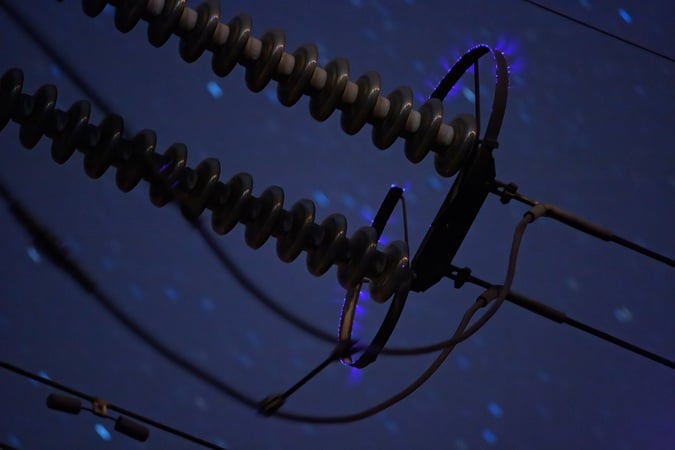
Figure 1. Corona discharge on a high-power transmission line. Image used courtesy of Adobe Stock
Though it doesn’t result in a full breakdown or arcing between conductors, corona discharge has the potential to cause power loss, ozone formation, and both audible and radio frequency (RF) noise. In high-voltage transmission lines, particularly those operating above 100 kV, these effects can be significant.
In the first half of this article, we’ll cover the causes and effects of corona formation in transmission lines. We’ll also learn how to estimate the severity of corona losses using Peek’s formula. In the article’s latter portion, we’ll discuss several conductor design techniques that either help prevent corona discharge or lessen its adverse effects.
How and When Corona Discharge Forms
As stated above, corona discharge occurs when the electric field near the surface of a conductor becomes intense enough to ionize surrounding air molecules. It’s especially likely at sharp edges or points of surface irregularity. Once the air is ionized, it becomes conductive. It allows small currents to pass through the ionized region, forming a self-sustaining plasma known as corona.
Under standard conditions, the threshold for corona formation is typically in the range of 30 kV/cm in dry air. However, the onset of corona discharge depends on multiple variables, as does its intensity. Conductor surface condition plays a major role—rough, dirty, or weathered conductors initiate corona at lower voltages than polished, clean conductors due to higher local electric field concentrations.
Conductor diameter is another critical factor. Larger conductors distribute the electric field more evenly and thus raise the corona onset voltage. This principle is central to one of the mitigation techniques we’ll discuss later on, namely the use of bundled conductors in extra-high-voltage (EHV) and ultra-high-voltage (UHV) lines.
Line voltage level obviously correlates with corona severity—voltages above 220 kV almost invariably require special consideration for corona control. Humidity, rain, fog, and snow also exacerbate corona formation. In these wet conditions, water droplets on the conductor surface distort the local field and create transient high-field regions that are conducive to ionization.
Adverse Effects of Corona Discharge
When it comes to the performance and efficiency of transmission lines, corona has several detrimental effects. One important issue is power loss, which occurs due to leakage currents in the ionized air surrounding the conductor. Although small in percentage terms (typically < 1% for well-designed lines), this loss is continuous. The amount also increases under adverse weather conditions.
Another concern is radio interference, particularly in the medium-frequency (MF) and high-frequency (HF) bands. This interference, which occurs due to electromagnetic emissions from ionized particles accelerating in the electric field, is especially problematic near residential or other populated areas. Rapid ionization and deionization cycles also produce audible noise in the range of 1 to 20 kHz, which can be a nuisance near substations or heavily loaded lines.
Finally, corona produces ozone (O₃) and nitrogen oxide (NOₓ) through high-energy collisions of electrons with atmospheric gases, contributing to environmental concerns and potential insulation degradation over time.
Calculating Corona Losses: Peek’s Formula
Peek’s formula, which was originally developed through empirical observation, is commonly used to quantify corona power loss. It’s given by:
$$P~=~241~\times~10^{-5}~\times~(\frac{f~+~25}{\delta})~\times~\sqrt{\frac{r}{D}}~\times~(V~-~V_0)^2 \quad \text{[kW/km/phase]}$$
Equation 1.
where:
P = Corona power loss (W/km/phase)
f = Frequency of the line (Hz)
δ = Air density factor (function of altitude and temperature)
r = Radius of conductor (cm)
D = Spacing between conductors (cm)
V = Line-to-neutral voltage (kV)
V0 = Corona inception voltage (kV).
Note that this formula assumes fair weather.
V0 is a function of conductor geometry, atmospheric conditions, and surface irregularity. It can be estimated by:
$$V_0~=~m_0\times r \times g_0 \times \delta \times \ln(\frac{D}{r})$$
Equation 2.
where:
m0 = Surface irregularity factor (typically between 0.8 and 1.0)
g0 = Breakdown strength of air (kV/cm) at STP
D = Equivalent spacing between conductors (cm)
Peek’s formula provides a reliable basis for preliminary corona loss calculations. However, modern high-voltage design also uses finite-element field simulations and EMTP-type software tools for more accurate modeling, especially under transient or non-uniform conditions.
Corona Mitigation Techniques
As transmission voltage levels increase beyond 220 kV, the design and operation of overhead lines must explicitly account for corona discharge and its adverse effects. To reiterate, these effects include:
- Increased line losses.
- Electromagnetic interference.
- Audible noise.
- Environmental byproducts (O₃ and NOₓ).
To reduce the severity of corona and improve system efficiency and reliability, several engineering techniques are employed. Along with anti-corona rings, the most prominent of these are the use of bundled conductors, conductor surface treatment, and increased conductor diameter. All of these methods target a reduction in electric field intensity at the conductor surface, which is the primary factor initiating corona discharge.
Bundled Conductors
One of the most effective strategies for mitigating corona discharge is the use of bundled conductors. These consist of two or more subconductors spaced uniformly by non-conductive spacers. This configuration reduces the surface voltage gradient by effectively increasing the radius of the conductor system without a corresponding increase in conductor material.
The electrostatic field around a cylindrical conductor is inversely proportional to its radius. As a result, distributing the phase current across multiple subconductors significantly reduces the local electric field strength at any point on the conductor surface. Mathematically, for a single conductor of radius r, the maximum electric field at the surface in a parallel conductor system is approximated by:
$$E~=~\frac{V}{r~\times~\ln(\frac{D}{r})}$$
Equation 3.
where:
V is the line-to-neutral voltage
D is the distance between conductors.
For a bundled conductor consisting of n subconductors, the equivalent bundle radius (rb) is given by:
$$r_b~=~ \sqrt[n]{r~\times~s^{n-1}}$$
Equation 4.
where s is the spacing between subconductors.
This increased effective radius results in a lower surface electric field, delaying the onset of corona. As a result, bundled conductors are standard in EHV (≥ 345 kV) and UHV (≥ 765 kV) systems. They also help reduce radio interference and audible noise and improve thermal performance due to enhanced surface area.
Conductor Surface Treatment
Corona discharge is highly sensitive to surface irregularities on the conductor. These irregularities lead to localized field intensification, which can significantly lower the disruptive voltage threshold. This causes corona activity to occur more quickly.
Conductor surface treatment methods are essential in minimizing such field concentrations. One common method is mechanical polishing, which smooths out micro-roughness and burrs on the conductor surface. More advanced treatments include the application of corona-resistant coatings or epoxy-based enamel layers, although these are more prevalent in high-voltage laboratory conductors or submarine cables due to environmental exposure risks.
Anti-Corona Rings
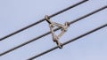
In high-voltage substation terminals and transmission line ends, anti-corona rings like the one in Figure 2 are frequently employed. These are also known as grading rings.
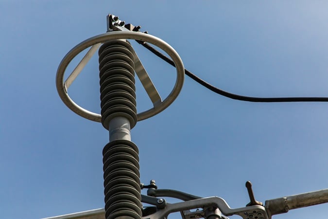
Figure 2. An example of an anti-corona ring. Image used courtesy of Adobe Stock
These toroidal metallic rings are installed at points of high electric field concentration—at the termination of line hardware or insulators, for example—to uniformly distribute the field and lower peak intensity. They function by increasing the radius of curvature at the critical junctions, thereby mitigating local ionization. Analytical and simulation tools such as the Finite Element Method (FEM) are often used to optimize ring dimensions and placement based on field contour studies.
Increased Conductor Diameter
Another approach to suppressing corona discharge is to increase the physical diameter of the conductor. From electrostatic field theory, the electric field at the surface of a cylindrical conductor in a multi-phase arrangement is inversely related to its radius. Increasing the diameter therefore decreases the surface field for a given line voltage. This method is particularly beneficial in single-conductor systems where bundled conductors may not be economically justifiable.
The choice of conductor diameter must balance mechanical, electrical, and economic considerations. Larger diameters result in higher weight, affecting sag and tension requirements, and increase wind and ice loading. As such, aluminum conductor steel-reinforced (ACSR) or all-aluminum alloy conductors (AAAC) are often chosen for larger-diameter designs. This helps the conductor to maintain a low mass-to-conductance ratio.
The following table shows the relationship between conductor diameter and corona inception voltage for a typical EHV line under standard atmospheric conditions (δ = 1.0).
Table 1. Relationship between conductor diameter and corona inception voltage for a typical EHV line.
| Conductor Diameter (mm) | Corona Inception Voltage (kV rms) |
| 18 | 186 |
| 25 | 225 |
| 32 | 258 |
| 38 | 282 |
| 45 | 305 |
This clearly illustrates that an increase in conductor diameter significantly elevates the corona inception voltage, thereby extending the safe operating margin for high-voltage transmission.
Key Takeaways
Understanding corona discharge and its mitigation is essential for the efficient and reliable operation of high-voltage transmission systems. Uncontrolled corona can lead to significant energy losses, degradation of power quality, and interference with communication networks—issues that are particularly critical in densely interconnected grids and long-distance transmission corridors. By applying appropriate mitigation techniques, these undesirable effects can be minimized.
Countinue reading this article series wtth Part 5: "A Guide to Electromagnetic Interference in High-Voltage Transmission Lines."