Facebook
 Google
 GitHub
 Linkedin
Sustainability and Energy Efficiency Benefits of Lead-Free Soldering
Learn how lead-free soldering offers a sustainable, energy-efficient solution for power module assembly. It achieves up to 55% energy savings and ensures compliance as the RoHS 7(a) exemption nears its 2027 expiration.
Article co-authored by Littelfuse's Dr. Sonja Madloch.
This article is published by EEPower as part of an exclusive digital content partnership with Bodo’s Power Systems.
This story investigates the transition from high-lead (PbSn5Ag2.5) to Pb-free solder in power module assembly in response to the anticipation of the currently scheduled RoHS Exemption 7(a) expiry in 2027, subject to possible future extension or renewal. The results confirm that Pb-free soldering offers an energy-efficient alternative, supporting both regulatory alignment and sustainability targets.
High-lead (PbSn5Ag2.5) solder alloys containing more than 85% lead by weight have long been utilized in power module assembly due to their ductility and mechanical robustness under cycling conditions. Their high melting point allows multiple soldering steps without reflowing previously formed joints, while their intrinsic ductility helps absorb the thermal stress during power cycling.
These characteristics have made high-Pb solders the standard choice for demanding applications such as die-attach, terminals, clips, and substrate-to-baseplate bonding in power semiconductor modules. However, the use of lead presents significant environmental and health risks, which have led to increasing regulatory restrictions across global markets.
In the European Union, the Restriction of Hazardous Substances (RoHS) Directive limits the use of lead in electrical and electronic equipment to a maximum concentration of 0.1% by weight in homogeneous materials [1]. Until now, widespread use of high-Pb solder in power modules has been permitted under Exemption 7(a), which allowed lead in high-melting-point solder (≥85% Pb).
This broad exemption, originally adopted in 2003, has enabled the continued use of high-Pb solder in industrial power electronics. RoHS Exemption 7(a) expires on 31 December 2027, though it is subject to possible future extension or renewal [1].
In response to these regulations, the market adapted in a way by offering more Pb-free solutions (SAC alloy system, SnSb system, Transient liquid phase sintering). This article presents a case study evaluating the transition from high-Pb to Pb-free solder across two representative power modules (M1&M5). The investigation compares both processes in terms of lead consumption, soldering reflow profiles, energy consumption, and CO2 emissions reduction potentials
The study was conducted under real-world manufacturing conditions, using a calibrated energy monitoring system during reflow soldering in a vacuum furnace. Figures and tables support the discussion of experimental results and highlight the sustainability and economic advantages of the Pb-free assembly process. The findings are discussed in the context of upcoming regulatory deadlines and offer practical insights into the readiness of Pb-free technology for industrial power module production.
Experimental Methods
Two power semiconductor modules were selected for this study, named M1 and M5. Module M1 was chosen for its complex design and high thermal mass, whereas module M5 was selected for the high-runner product. These modules are representatives of high-volume industrial production and similar assembly processes.
Conventional soldering of these module assemblies was done using a PbSn5Ag2.5 solder alloy. These modules were examined to assess energy consumption differences between soldering processes, both subject to the same vacuum soldering furnace (Budatec VS320). In the new assembly process, this high-Pb solder was replaced with a Pb-free alternative such as SAC alloy. All other materials, including substrates, terminals, baseplates, and dies, remained unchanged.
Table 1. Reflow Soldering Conditions for M1 and M5 Modules
| Module | Capacity per run | Solder | Reflow temp [°C] |
| M1 | max | Pb | 410 |
| M1 | max | Pb free | 255 |
| M5 | max | Pb | 380 |
| M5 | max | Pb free | 255 |
Table 1 summarizes the soldering conditions and reflow temperatures applied to the two representative module families. The Pbbased reference was soldered at reflow temperatures of 380 °C and 410 °C as shown in Figure 2.
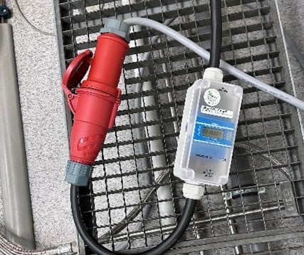
Figure 1. Eltako DSZ180CEE-32A MID 28032128 three-phase meter digital 10 A. Image used courtesy of Bodo’s Power Systems [PDF]
These profiles involved direct ramp-up to peak temperature and extended time-above-liquidus (300 s). For the Pb-free soldering process, a controlled thermal profile was used with a reflow temperature of 255 °C. A preheat step at 160 °C with 120 s dwell time was introduced to activate flux and remove volatiles. The temperature was then ramped to peak, followed by a short vacuum stage (1 mbar) to support void reduction and flux residue removal. Final cooling was carried out under nitrogen to minimize thermal stress and intermetallic growth.
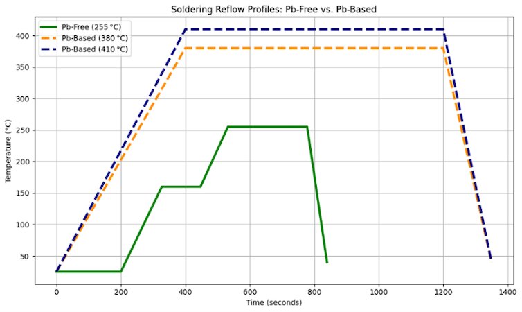
Figure 2. Soldering reflow profiles for Pb-based (380 °C and 410 °C) and Pb-free (255 °C) processes. Image used courtesy of Bodo’s Power Systems [PDF]
Electrical energy consumed by the furnace during each reflow run was recorded using a three-phase plug-in MID-certified electricity meter, shown in Figure 1. This portable metering device was connected directly to the furnace’s 400 V/50 Hz power supply and allowed precise logging of active energy consumption (kWh) per batch.
For each module and soldering condition, the average energy per run was determined by multiple measurement runs to ensure repeatability. The annual energy consumption and CO2 emissions for each module family can be calculated using the following equations. Exemplarily, Germany’s 2025 grid emission factor is given as 0.328 kg CO2/kWh [2]. Electricity costs can be calculated based on an industrial tariff e.g. 0.151 €/kWh [3].
1. Annual energy consumption potential
\(Energy\,Consumption(E_{total})=\Bigl(\frac{E_{r}}{C_{run}}\Bigr)*N\\E_{r}=energy\,consumption\,per\,run\\C_{r}=capacity(no.\,of\,modules)\,per\,run\\N=annual\,production\)
2. Annual CO2 emission potential
\(CO_{2}=(E_{m}*EF)*N\\E_{m}=Energy\,consumption\,per\,module\\E_{F}=CO_{2}\,emission\,factor\)
3. Energy consumption reduction potential
\(\Delta E=E_{Pb}-E_{Pb\,free}\)
4. CO2 reduction potential
\(\Delta CO_{2}=CO_{2}^{\,\,Pb}-CO_{2}^{\,\,Pb\,free}\)
Together, this methodology allowed direct comparison of energy, emissions, and cost between the high-Pb and Pb-free soldering processes under real production-scale conditions. The results of this comparison are presented and analyzed in the following Results and Discussion section.
Results and Discussion
Two energy metrics were used to assess the effect of switching from high-Pb to Pb-free soldering: (i) electricity consumption per run and (ii) energy consumption and CO2 emissions per module. The per-run values represent the total electricity consumed by the soldering furnace during one complete operating cycle, measured while the process was operated at maximum loading capacity.
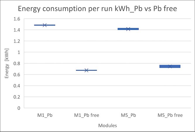
Figure 3. Energy Consumption per furnace Run for Modules M1 and M5 under Pb and Pb-Free soldering. Image used courtesy of Bodo’s Power Systems [PDF]
Figure 3 illustrates that under these max-capacity runs, a major decrease was observed with the Pb-free process. For module M1, the per-run electricity demand drops from approximately 1.49 kWh with the high-Pb solder to 0.68 kWh with the Pb-free solder. Similarly, module M5’s energy requirement decreases from about 1.42 kWh to 0.75 kWh per run, indicating that Pb-free soldering requires approximately half the run-level energy compared with the high-Pb process.
Table 2. Energy Consumption and CO2 Emissions, for High-Pb and Pb-Free Soldering Processes (M1&M5)
| Module. | Solder material. | Reflow temp [°C]. | Energy consumption [kWh]. | CO2 [kg]. | |
| 1 | M1 | Pb | 410 | 0.165 | 0.054 |
| 2 | M5 | Pb | 380 | 0.118 | 0.039 |
| 3 | M1 | Pb free | 255 | 0.075 | 0.025 |
| 4 | M5 | Pb free | 255 | 0.062 | 0.020 |
As shown in Table 2, energy consumption and CO2 emissions were evaluated per module for M1 and M5 under both Pb-based and Pb-free soldering conditions. Module M1 showed a decrease in energy consumption per module from 0.165 kWh in the high-Pb process to 0.075 kWh after switching to Pb-free solder, corresponding to an energy saving of more than 55%. Similar trends were observed in M5 from 0.118 kWh to 0.062 kWh reduction energy saving around 48%
This corresponds to reductions in CO2 emissions from 0.053 kg to 0.024 kg for M1, and from 0.038 kg to 0.020 kg for M5, based on Germany’s 2025 average grid emission factor of 0.32 kg CO2/kWh. The measured data revealed that M1 exhibits higher energy consumption in the same Pb-free process (peak T=255°C) compared to M5. This difference is primarily attributed to the higher thermal mass of M1. Heavier module designs and higher material volume require additional heat input to reach target soldering temperatures.
The main driver in energy reduction between M1 and M5 is primarily attributed to the differences in their original Pb-based reflow temperatures. For module M1, the high-Pb process operated at a reflow temperature of 410 °C, whereas for M5, the peak was 380 °C. Since both were transitioned to the same Pb-free process at 255 °C, M1 experienced a larger absolute temperature drop (155 °C) compared to M5 (125 °C).
This reduction of over 125 °C significantly reduces furnace energy demands [4]. Studies have shown that even a modest 35 °C reduction in peak reflow temperature can yield around 10% energy savings in industrial furnaces [4]. The 125–150 °C decrease achieved in this case explains the nearly 50% energy reduction observed. Despite these lower temperatures, the Pb-free process maintained full compatibility with production quality requirements.
All modules passed standard optical inspection, isolation tests, and electrical validation after soldering. These findings reinforce the practicality and industrial relevance of transitioning to Pb-free soldering in power module assembly, combining process optimization with regulatory readiness and sustainability-driven innovation.
Conclusion
This study demonstrates that Pb-free soldering has the potential to be a reliable and sustainable alternative for power module assembly. The transition eliminates significant lead usage (several tons/year, depending on production volume), lowers reflow temperatures, and achieves a 48% reduction in energy consumption and a reduction in CO2 emissions, along with meaningful cost savings. As RoHS Exemption 7(a) approaches its scheduled 2027 expiry, adopting Pb-free processes supports regulatory compliance while advancing environmental and operational efficiency in power electronics.
References
1. European Commission. (2025). Commission Delegated Directive (EU) 2025/1802 of 8 September 2025 amending Annex III to Directive 2011/65/EU of the European Parliament and of the Council as regards an exemption for lead in high melting temperature type solders. Official Journal of the European Union.
2. Nowtricity. (2025). German electricity CO2 intensity data (2024). Based on ENTSO-E grid reporting.
3. Eurostat. (2024). Electricity prices for non-household consumers – bi-annual data (from 2007 onwards). European Commission Statistics Database. Retrieved from
4. Murling, A., Zhang, J., & Hotvedt, C. (2024). Energy consumption reduction using low-temperature solder alloys. Indium Corporation.
This article originally appeared in Bodo’s Power Systems [PDF] magazine and is co-authored by Mani Krishna Swami Puppala and Sonja Madloch, Littelfuse