Facebook
 Google
 GitHub
 Linkedin
Understanding Alternating Voltage Generation
The generation of alternating voltage is a fundamental concept in electrical engineering that involves the production of an electrical signal that periodically changes direction, magnitude, and frequency. Alternating voltage is widely used in various applications, from power generation and transmission to consumer electronics, and its generation relies on the principles of electromagnetic induction
An alternating current (AC) continuously reverses direction, alternately flowing in one direction and then in the other. Alternating voltage can be similarly described. Usually, AC voltages and currents are sinusoidal and definite relationships exist among the peak, average, and effective values.
Consider two series-connected conductors rotating in a magnetic field, as illustrated in Figure 1. Conductors 1 and 2 form a loop within the field set up between the two magnetic poles. The conductors are mechanically fastened to an axle equipped with a crank for hand turning. Each conductor is connected to a slip ring, and the slip rings have brushes for electrically connecting to the external terminals (A and B). When the loop is rotated, the conductors cut (or brush through) the magnetic flux, causing an emf to be generated in each conductor.
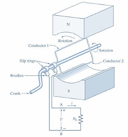
Figure 1. Simple alternating voltage generator consisting of a conducting loop rotated in a magnetic field. An EMF is induced in each conductor (and produced at the output terminals) as the conductors are swept past the magnetic poles. The EMF reverses polarity when the conductors move from one pole to another. Image used courtesy of Amna Ahmad
Figure 2 illustrates the conditions at each of several instances while the loop is being rotated in the magnetic field. These can be explained as follows.
Loop is Horizontal
Figure 2(a): The loop is horizontal, and conductor one is moving up while conductor two is moving down. Because the motion of each conductor is parallel to the direction of the magnetic field at this instant, no flux is being cut by the conductors, so no EMF is generated. As illustrated by point ‘a’ on the graph of voltage (e) versus time (t), the voltage at the output terminals (A and B in Figure 1) is zero.
Conductors Move at an Angle
Figure 2(b): The conductors are now moving at an angle across the field, so each is cutting some flux, and an EMF is induced in each conductor. According to Lenz’s law, the direction of the induced EMF must be such that it opposes the motion that causes the EMF. So, the EMF induced in conductor one causes a current to flow toward the viewer, as illustrated. This current produces a counterclockwise magnetic flux around the conductor, which strengthens the magnetic field in front of the conductor and weakens it behind (i.e., it opposes the motion of the conductor).
Similarly, the induced EMF in conductor 2 causes a current in the direction shown, away from the viewer. A clockwise flux is set up around conductor 2, which again weakens the flux behind conductor two and strengthens it ahead of the conductor, opposing the motion of the conductor. It is seen that the current directions in the two conductors are such that they assist each other [i.e., the current is flowing around the loop (in Figure 1) in a single direction].
Consequently, the output voltage is positive at terminal A and negative at terminal B. (Conductor 1 is connected to A, and conductor two is connected to B.) A current flows in the direction shown (from A to B) through the external load RL. When the growth of the terminal voltage e is plotted versus time t, the result is illustrated by the graph (or waveform) in Figure 2(i). Point ‘a’ represents the zero-output voltage obtained for the conditions in Figure 2(a), and point ‘b’ is the output voltage sometime later when the conductor positions are as shown in Figure 2(b).
Conductors Move Perpendicular to the Magnetic Field
Figure 2(c): The conductors now move perpendicular to the magnetic field. So, they are cutting maximum flux and generating maximum EMF. Again, the current directions assist each other so that current flows around the loop and terminal A remains positive while terminal B is negative. The output current through RL is now greater than before, and as shown on the graph of e-versus-t, the output voltage has reached a peak value, point ‘c.’
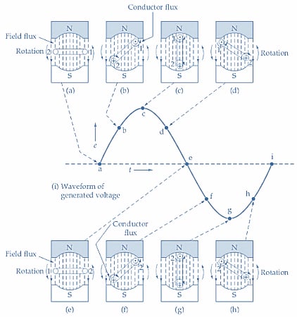
Figure 2. A sinusoidal voltage waveform is generated at the terminals of a conducting loop rotating in a magnetic field. The peak output voltage is produced when the conductors are moving perpendicular to the field [see (c) and (g)]. Zero output is generated at the instants when the conductors are moving parallel to the field [see (a) and (e)]. Image used courtesy of Amna Ahmad
Conductors Move at an Angle Less Than 90o
Figure 2(d): Now, the conductors are again moving at an angle less than 90° for the direction of the magnetic field. So, the amount of flux being cut is reduced, and consequently, the generated EMF is less than for the conditions in Figure 2(c). The current direction and output voltage polarity are the same as before. However, the output voltage has now dropped below the peak level, as shown at point ‘d’ on the e-versus-t graph.
Conductors Move Parallel to the direction of the Magnetic Field
Figure 2(e): At this time, the conductors are again moving parallel to the direction of the magnetic field. No flux is being cut, so no EMF is generated. The output voltage is zero and is plotted at point ‘e’ on the voltage-versus- time graph.
Conductors Move at an Angle
Figure 2(f): The conductors are once again moving at an angle concerning the direction of the magnetic field. However, both conductors now have the induced current directions reversed. The current direction in conductor one is flowing away from the viewer, while that in conductor two is toward the viewer. It is seen that the currents still assist each other so that the current around the loop still has a single (but reversed) direction. The output voltage is now such that terminal B (in Figure 1) is positive, while terminal A is negative. The instantaneous output voltage plotted versus time gives point ‘f’ on the graph.
Conductors Move Perpendicular to the Magnetic Field
Figure 2(g): The motion of the conductors is once again perpendicular to the magnetic field, and maximum flux is being cut. So, maximum EMF is again generated. The output voltage is still a negative quantity and has reached its peak value, plotted at point ‘g’ on the e-versus-t graph. It is easily seen that as the loop rotation continues, the output voltage goes to zero once more, then reverses again, and the cycle is repeated over and over.
Because the voltage generated by the rotating loop is alternately positive and negative, it is referred to as an alternating voltage. The current produced in a load supplied by an alternating voltage flows first in one direction and then in the other. So, it is an alternating current. The designation AC is normally applied to both current and voltage. The voltage/time graph in Figure 2(i) is called an AC waveform.
Takeaways of Alternating Voltage Generation
Alternating voltage generation is a crucial concept in electrical engineering that has shaped the modern world. The ability to produce a voltage that predictably changes direction and magnitude has enabled the development of a wide range of electrical systems and devices. The process relies on the principles of electromagnetic induction, which is the basis for operating generators, motors, and transformers.
Featured image used courtesy of Adobe Stock