Facebook
 Google
 GitHub
 Linkedin
Calculating Transformer Currents
The article explains the calculation of transformer currents using the power formula and turns ratio and looks at transformer impedance and short-circuit current, emphasizing the importance of understanding them for electrical system safety.
Safeguarding power systems requires a firm grasp of transformer currents. Accurate calculations ensure optimal performance, prevent equipment damage, and protect personnel. By understanding the intricacies of power formulas, turn ratios, and short-circuit currents, efficient and reliable electrical networks can be built.
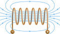
First, a little terminology: The transformer's coil with a voltage applied to it is always called the primary coil, or primary winding, and the voltage applied is always called the primary voltage (VP). The coil that has a voltage induced in it by the magnetic field of the primary winding is always called the secondary coil, or secondary winding, and the voltage induced in it is called the secondary voltage (VS). If we know the number of turns on the primary and secondary windings, the value of one of the currents can be calculated if the other current is known.
![]()
Image used courtesy of Unsplash
Solving for Transformer Currents Using the Power Formula
There are only two rules needed to calculate any values in a transformer circuit:
\[\frac{Volts_{Pri}}{Volts_{Sec}}=\frac{Turns_{Pri}}{Turns_{Sec}}\]
Power In = Power Out
Let’s see how we can use the second rule for transformers to determine voltage or current value. The second rule states that power into a transformer is equal to the power out:
\[V_{P}\times I_{P}(Power\,In)=V_{S}\times I_{S}(Power\,Out)\]
Look at the following example: A transformer is supplied with 240 volts to the primary winding. The secondary winding voltage is 30 volts. A load is connected to the secondary that draws 1.6 amps. How many amps must flow in the primary winding?
Power Out = 30 V × 1.6 A = 48 VA
Power In = 48 VA
So, the amperage must equal the power divided by the volts:
\[\frac{48VA}{240V}=0.2A\]
If the power is the same in both primary and secondary windings and the voltage in the primary winding is 8 times larger, then the current in the primary winding must be one-eighth as much as the current in the secondary winding; otherwise, the power in each winding would be different. In general terms, if the voltage in one winding is one-eighth as much as the voltage in the other winding, the current in the first winding must be 8 times larger, or the power would not be the same.
Here is an example: A transformer has a voltage of 480 volts applied to the primary winding and 2 amps of current flow through the winding. If the secondary winding has a voltage of 48 volts induced, how many amps must flow in the secondary winding?
Since the primary winding voltage is 10 times greater than the secondary winding voltage, and power in has to equal power out, the current through the primary winding must be one-tenth as much as the current through the secondary winding. The equation would look like this:
\[2\,Amps\,Primary=\frac{1}{10}\times Amp\,Sec\]
Multiplying both sides of the equation by 10 gives us the following:
Amps Secondary = 2 Amps Pri × 10 = 20 Amps Sec
To check your answer:
Power In = Power Out
\[V_{P}\times I_{P} = V_{S}\times I_{S}\]
480 V × 2 A = 48 V × 20 A
Solving for Transformer Currents Using the Turns Ratio
We can also use the turns ratio to calculate voltage or current or both, as long as we know the ratio and one voltage value and one current value.
Turns ratio of a transformer is 5 to 1; the primary voltage is 120 volts, and the secondary current is 12 amps. What are the secondary winding voltage and the primary amperage?
Because the ratio of turns is equal to the ratio of voltages:
\[\frac{5}{1}=\frac{120V_{Pri}}{V_{Sec}}\]
\[V_{Sec}=\frac{120_{Pri}}{5}=24V_{Sec}\]
For power in to equal power out, the turns ratio must be inverse to the current ratio:
\[\frac{I_{S}}{I_{P}}=\frac{N_{P}}{N_{S}}\]
\[\frac{12\,Amps\,I_{S}}{I_{P}}=\frac{5\,Turns\,Pri}{1\,turn\,Sec}\]
\[I_{P}=2.4\,Amps\]
Because the primary voltage is 5 times larger than the secondary voltage and the power in is equal to the power out, the secondary current must be 5 times greater than the primary current:
\[\frac{12\,Amps\,I_{S}}{5}=2.4\,Amps\,I_{P}\]
To check your work, power in must equal power out:
\[120\,V_{P}\times2.4\,Amps\,I_{P}=24\,V_{S}\times12\,Amps\,I_{S}\]
No matter what values you are calculating, the power out of the transformer must equal the power into the transformer; otherwise, your calculations will be incorrect.
Transformer Impedance and Short-Circuit Current
Like all AC electrical devices, transformers have internal impedance, which opposes AC flow. With transformers, the impedance is represented by the symbol Z and is expressed as a percentage. The impedance is the vector sum of the inductive reactance and the resistance of the transformer windings. When a winding of the transformer is short-circuited, this impedance is all that limits the total current that can flow. This maximum available short-circuit current is the starting value used to determine the interrupting rating of fuses and circuit breakers for larger transformers. The fuse or circuit breaker must be able to safely interrupt the maximum short-circuit current available where they are located in the circuit. The impedance of the wires in the circuit and other factors must also be taken into account and will make the actual value of the maximum available short-circuit current at the overcurrent device less than the value calculated using only the transformer impedance Z.
We could find this maximum available short-circuit current by connecting some large conductors between the secondary terminals of the transformer and applying rated voltage to the primary. Without a load on the transformer secondary, only the transformer and conductor impedance would limit current flow. An ammeter could measure the current value, but this excessive current flow would damage the transformer.
Determining Transformer Impedance With a Variable Primary Voltage
Another way to measure the maximum available short-circuit current indirectly without applying full voltage to the transformer primary is to short-circuit the transformer secondary winding and place an ammeter so we can read the secondary current. Connect a variable voltage source to the transformer's primary winding and gradually increase the voltage while reading the secondary current. When the secondary current equals the rated full load current of the transformer secondary, stop increasing the voltage and read the value of the primary voltage. In this way, the transformer's secondary winding is never subjected to more than its rated current. The applied primary voltage you read will be much less than the rated primary voltage because it will only take a small secondary voltage to move a large amount of secondary current because there is little or no opposition to current flow on the transformer's secondary. The applied voltage you read will be a certain percentage of the rated primary voltage. The impedance value listed on the transformer nameplate is this percentage. The symbol for the impedance is %Z. This percentage represents the percentage of rated primary voltage that is applied to the primary to produce full load current on the secondary of the transformer when it is short-circuited.
Calculating Available Short-Circuit Current
The secondary current flowing is a percentage of the total current that could flow if the full-rated voltage was applied to the transformer primary. This total current that could flow is the maximum available short-circuit transformer current. The formula to calculate this total current—the available short-circuit current (ASCC) is:
\[\frac{Rated\,Full-Load\,Secondary\,Current}{\%Z\,(expressed\,as\,a\,decimal)}=ASCC\]
For example: A 480 – 240-V, 25 KVA transformer has a %Z of 4%. How many volts must be applied to the 480-volt primary winding to allow the full-load secondary amps to flow when the secondary winding is short-circuited?
%Z is the percentage of 480 volts applied to the primary to get full-load secondary current to flow. Therefore, 4% of 480 volts is the applied voltage: 480 x 0.04 = 19.2 volts.
What is the maximum available short-circuit current of the transformer secondary?
The full-load rated secondary current of a 25 KVA, 240-volt transformer equals:
\[\frac{25\,KVA}{240 V}=104\,Amps\]
104 amps is 4% of the maximum available short-circuit current; therefore, the maximum available short-circuit current at the transformer equals:
\[\frac{104\,Amps}{0.04(\%Z\,expressed\,as\,a\,decimal)}=2600\,Amps\]
Calculating Transformer Currents
Understanding and applying the calculations of transformer currents, including power formulas, turn ratios, and considerations for impedance and short-circuit currents, is crucial in power system applications. These principles form the foundation for ensuring optimal electrical network performance, efficiency, and safety. Properly calculated short-circuit currents facilitate power system design, operation, and maintenance, contributing to their reliability and adherence to safety standards.