Facebook
 Google
 GitHub
 Linkedin
Improve Motor Lifetime With Slew Rate Control Gate Drive Optocoupler
Learn how Slew Rate Control (SRC) gate drive optocouplers mitigate high dv/dt from PWM in VSDs, reducing motor overvoltage, EMI, and power loss, thus extending motor life.
This article is published by EEPower as part of an exclusive digital content partnership with Bodo’s Power Systems.
Variable Speed Drives (VSD) uses Pulse Width Modulation (PWM) technique in modern electrical drives in industries where precise control of motor speed and efficiency are paramount. PWM technique controls the amount of power delivered to electrical devices by modulating the width of pulses in a square wave signal. While PWM offers precise control and efficient power management, its implementation can significantly affect the rate of change of voltage over time (dv/dt) in electrical drives. The primary mechanism through which PWM affects dv/dt is by introducing rapid voltage transition, leading to higher peak voltage level.
As the cable length increases, the impedance of the cable also increases due to its inductance and capacitance. The increase in impedance results in higher voltage spikes and dv/dt at the motor terminals. The elevated dv/dt level induced by long cable lengths can stress the insulation of motor windings and cause electromagnetic interference (EMI). High dv/dt causes partial discharge, insulation aging, and insulation failures, compromising the reliability and safety of the motor system. To mitigate these effects, various measures such as using shielded cables and passive filters are often implemented.
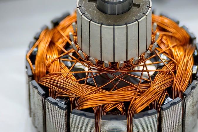
Image used courtesy of Adobe Stock
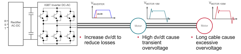
Figure 1. High dv/dt Causes Excessive Overvoltage. Image used courtesy of Bodo’s Power Systems [PDF]
Effect of Cable Length on Motor Lifetime
The length of the cable between the VSD and the motor plays a significant role in the performance and reliability of the motor system. Figure 2 estimates the overvoltage spike with reference to the bus voltage with increasing cable length. Using a 1200 V/600 A IGBT module as an example, the typical bus voltage is 600 V with allowable overvoltage not exceeding the absolute maximum ratings of 1200 V. The 600 A IGBT module switches around 100 ns. Based on this switching time and from Figure 2, the maximum allowable length is approximately 70 ft before the overvoltage exceeds 2 times the bus voltage at 1200 V.
Figure 3 shows an estimation of the motor wire insulation life with reference to cable length. Using the same example of a 1200 V/600 A IGBT module with 100 ns switching time. The cable length can vary from 10 ft to 70 ft before the overvoltage exceeds 2 times the bus voltage. This translates to 60,000 hours or 6.8 years of motor wire insulation lifetime.
The long cable can affect the overvoltage spikes and reduce the lifetime of the motor wire insulation. However, it is unavoidable to have a long cable connection between the VDS and motor in a factory environment. Therefore, it is critical to mitigate these effects by controlling the PWM dv/dt to an acceptable level.
Standards for VSD Admissible Voltage and EMI
The IEC and NEMA standards provide guidelines for admissible voltages for various motor types in Figure 4. For US NEMA standards, if we used the fastest rise time of 200 ns, the permissible dv/ dt ranges from 6 to 9 kV/µs. For international IEC standards widely adopted in Europe, the fastest rise time of 100 ns will derive a permissible dv/dt ranges from 10 to 20 kV/µs. Adding margin, The VSD will need to control the PWM dv/dt at a range of 4 to 15 kV/µs to prevent the overvoltage from exceeding the limits of the standards.
Electromagnetic interference (EMI) is also an increasing problem for VSDs that operate at higher frequencies, and IGBT switches faster. The higher dv/dt will generate more EMI signal errors to other nearby industrial equipment. CISPR 11 is the international product standard for EMI disturbances for industrial, scientific, and medical ISM equipment. VSD is classified under Class A, Group1 of the CISPR 11 for industrial equipment. Figure 5 shows the conducted EMI emission limits for industrial motor drives. Therefore, it is also crucial to control the dv/dt to keep the EMI within the limits of the standard.
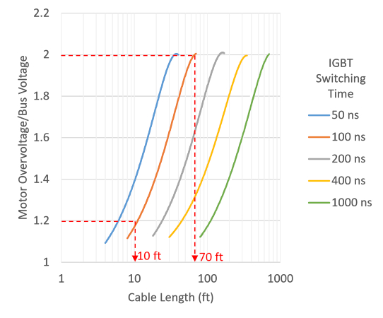
Figure 2. VSD to Motor Cable Length and Overvoltage [1]. Image used courtesy of Bodo’s Power Systems [PDF]
Limiting High dV/dt
A commonly used technique to mitigate dv/dt is installing a passive dv/dt filter between the VSD and the cable. The dv/dt filter consists of passive components: an inductor, a capacitor, and a resistor. The drawbacks of a passive filter are power loss, large filter size, and costs.
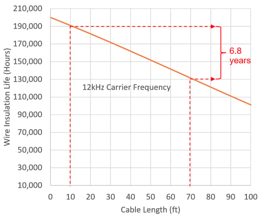
Figure 3. Motor Wire Insulation Life vs Cable Length [2]. Image used courtesy of Bodo’s Power Systems [PDF]
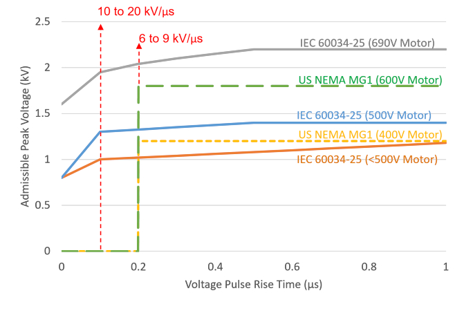
Figure 4. IEC & NEMA Standards of Admissible Withstand Overvoltage [3]. Image used courtesy of Bodo’s Power Systems [PDF]
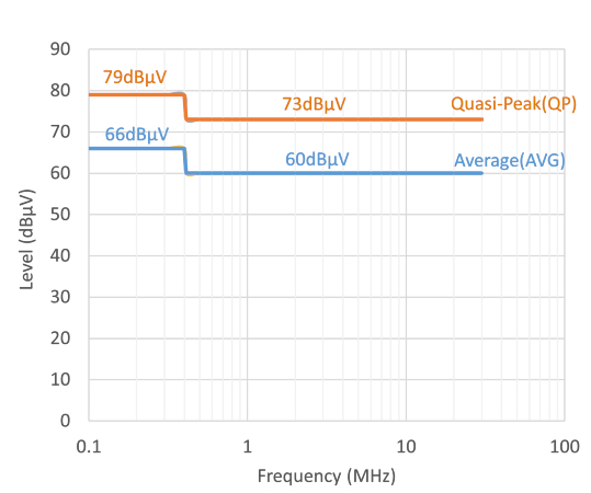
Figure 5. CISPR/EN 55011 Class A Conducted Emission Limits [4]. Image used courtesy of Bodo’s Power Systems [PDF]
On the other hand, the slew rate control gate driver offers a simple, small, and cost-effective alternative to the dv/dt filter. Based on the IGBT current feedback loop, the gate driver will control its current dynamically through the gate resistors. By varying the gate resistors, the dv/dt of the VSD can be controlled and not exceed the withstand voltage or EMI limits discussed earlier. This paper will discuss how the new Broadcom® gate drive optocoupler, ACFJ-3405, is used to control the dv/dt.
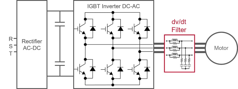
Figure 6. Passive dv/dt Filter Consists of Inductor, Capacitor and Resistor. Image used courtesy of Bodo’s Power Systems [PDF]
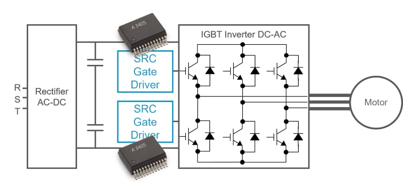
Figure 7. Slew Rate Control Gate Drive Optocoupler. Image used courtesy of Bodo’s Power Systems [PDF]
Slew Rate Control Gate Drive Optocoupler
The ACFJ-3405[5] is a 12A gate drive optocoupler with two selectable modes of output drive to optimize the slew rate of IGBT switching. It also features IGBT DESAT fault, IGBT gate fault, and system power supply fault monitoring, shutdown, and feedback to help meet VSD motor drive functional safety standards.
The ACFJ-3405 is packaged in a compact, surface-mountable 400 V CTI SO-24 package. This full-featured and easy-to-implement smart gate driver is certified to provide reinforced galvanic isolation meeting safety regulatory of the IEC/EN/DIN and UL/cUL.
Figure 8 shows a typical application diagram of the slew rate control (SRC) gate driver. The SRC gate drive optocoupler receives the PWM and SRC signals from the microcontroller. The PWM signals are then transmitted across the isolation barrier of the gate driver. The SRC signal will then select the outputs, VOP1 or both VOP1 and VOP2, in which the PWM signal will be sent to the gate of the IGBT. The microcontroller decides which mode of SRC levels based on the feedback of the IGBT or load current.
Figure 9 maps the IGBT current, IC, to the required gate current, to keep the dv/dt below the permissible dv/dt of 5 kV/us. At low IGBT current, for example, 40 A, the gate driver will deliver a low output current, IOP1, to keep the IGBT slew rate at 2.5 kV/us. On the other hand, in a design without slew rate control, a high gate current might cause the dv/dt to exceed the permissible limits at 6 kV/us at 40 A.
When the IGBT is switching at a higher current, for example, 120 A, the gate driver will deliver a higher gate current, IOP1 + IOP2, to switch the IGBT at a higher slew rate but still within the permissible target. However, by doing so, the dv/dt will be higher but optimized (see green dotted line), to reduce the switching losses.
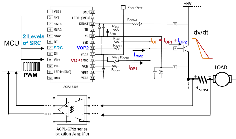
Figure 8. The Operation of Slew Rate Control Gate Driver. Image used courtesy of Bodo’s Power Systems [PDF]
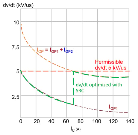
Figure 9. The Relationship of dv/dt, IGBT Current (IC), and Gate Driver Current. Image used courtesy of Bodo’s Power Systems [PDF]
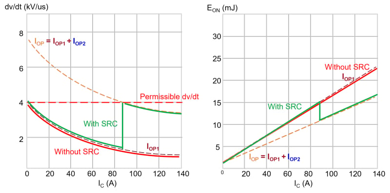
Figure 10. The dv/dt & EON of the 60 kW VSD with and without SRC. Image used courtesy of Bodo’s Power Systems [PDF]
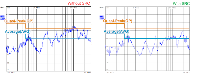
Figure 11. The EMI of the 60 kW VSD with and without SRC. Image used courtesy of Bodo’s Power Systems [PDF]
Effectiveness of the SRC Gate Driver
The effectiveness of the SRC gate driver is verified on a 60 kW VSD, using a 1200 V/200 A IGBT module with a cable length of 100 m. The permissible dv/dt is set at 4 kV/µs. The gate driver is set to switch from a lower gate current, IOP1, to a higher gate current, IOP1 + IOP2, when the IGBT current increases to 90 A. The results in Figure 10, denoted by the green line, show the dv/dt profile from 0 to 140 A with SRC. The red line denotes the dv/dt profile without SRC.
Although the green and red dv/dt lines are within the permissible dv/dt, the one with SRC will have a lower switching loss, as shown in the second plot of Figure 10. At 90 A, the SRC will switch the IGBT at a higher dv/dt and help to reduce the EON energy. Comparing the EON lines, the green EON line with SRC is 5 mJ lesser, which translates to lower overall power loss and higher efficiency.
Using the same 60 kW inverter with a 100 m cable setup, the conducted emission is measured with and without SRC, according to the CISPR 11 standard. The first plot in Figure 11 shows the EMI exceeding the standard of the conducted emission, quasi-peak, when the IGBT is switching at high dv/dt without SRC control. The second plot shows the optimized EMI without exceeding the quasi-peak with SRC control.
Summary and Conclusion
This article explains the benefits of the PWM technique and its side effects due to dv/dt. The long cable between the VSD and motor amplifies the dv/dt, causing EMI and overvoltage that reduce the motor lifetime. The article uses the standard for VSD admissible voltage to estimate the level of dv/dt that is permitted in different VSD operations. With the permissible dv/dt defined, the article compares how the SRC gate drive is more beneficial than the conventional solution of a passive dv/dt filter. These benefits were demonstrated by using ACFJ-3405, an SRC driver in a 60 kW VSD with a cable length of 100 m. Measurement results show that the dv/dt was kept below a permissible level of 4 kV/µs with lower switching loss and EMI better controlled to the CISPR 11 standard.
References
1. Application Paper “Applying dV/dT filters with AFDs,” Gerry Feldmeier and Dan Kupersmith, Eaton AP043001EN
2. Technical Guide “ Effects of AC Drives on Motor Insulation - Knocking Down the Standing Wave,” ABB ST-311-102
3. White Paper “An Improved Approach for Connecting VSD and Electric Motors,” Hue Vang and Marco Chiari, Schneider Electric
4. “EMC Standards,” Academy of EMC, https://www.academyofemc. com/emc-standards
5. Data Sheet “ACFJ- 3405 12A Gate Drive Optocoupler with Slew Rate Control and Functional Safety Features,” Broadcom Inc, ACFJ-3405-DS100
This article originally appeared in Bodo’s Power Systems [PDF] magazine.